Vodafone Huawei R216 teardown

For work reasons, we had a couple of these LTE mobile hotspots deployed permanently. After about two years, they’ve failed, both with puffed up batteries. For no good reason I can think of, the devices don’t work with the battery removed, they just blink constantly. Still, they worked well right up to that point, so, what’s in one? I’ve not tried powering one up again properly, I’m not excited about ordering a spare battery for one, and it’s not (currently) interesting enough to try and provide power to the right place to fake the battery.

You can find the FCC internal photos under QISR216 but it’s blurry. We know it’s from Huawei, but that’s about it. You can also find a GPL compliance tarball that implies it runs android, and has some more details if you’re good at digging into that sort of thing (I’m not really) R216-open resource code.tar.gz

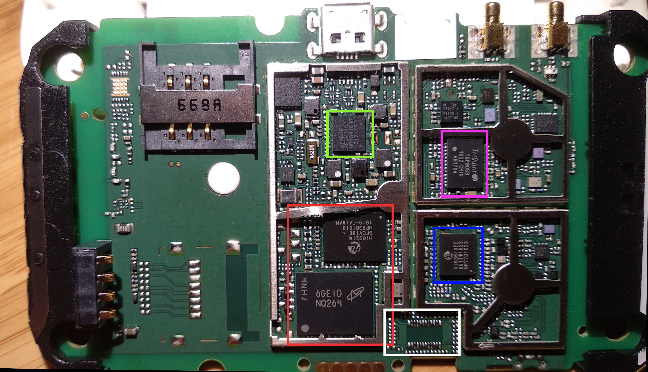
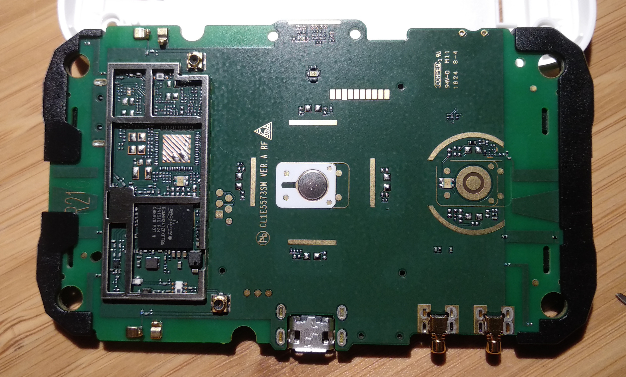
Here’s some photos of it’s guts with a bit of decoding. There’s a few spaces on the PCB for what I suspect is a SD card, and a 5GHz wifi radio, but it’s kinda ugly trawling through old product announcements to see if any of it was ever used. The row of circular pads on the PCB edge are actually available without disassembly, (there’s a row of holes inside the battery compartment that provides access to them), so that’s presumably a “useful” port for something. There’s another set of test pads by the wifi chip.

bcm43241 wifi chipset

The silver circle in the white field is actually a super slim pushbutton!

And now the “real” side

Green is HiSilicon HI6559, a PMIC from reading elsewhere. Red is some Micron flash, and a HiSilicon Hi6921M. You can read a bit more about the part here: https://github.com/Huawei-LTE-routers-mods/README/blob/master/balong_series.md

Blue is HiSilicon Hi6361gfc, presumably the LTE modem? Purple is the Qorvo multiband power amplifier

White box? No idea, not sure what would ever go on that footprint. The blank on the left is presumably a microsd socket.

There’s another one of these superslim membrane switches in the top right, between the micro usb and the optional external antenna connectors.

sunxi-fel: nanopi duo2 – latest kernel + openwrt rootfs

So yeah, back on getting all of that friendlyarm nanopi duo2 supported again. Want a newer kernel to get the bluetooth stuff in, but not interested in trying to port openwrt forwards (yet?) Instead, build your own kernel as per: http://linux-sunxi.org/Mainline_Kernel_Howto and build openwrt as normal. (well… normal, but add this patch to skip a manual step: https://github.com/karlp/openwrt/commit/6438d22e98df353afe2635667b7dc29c97bd1196 )

Now, make sure you _BUILT IN_ any kernel modules you want, because we aint doin no module installation and loading bullshit.

And then just…. fel load it, as per http://linux-sunxi.org/FEL/USBBoot#Booting_the_whole_system_over_USB_.28U-Boot_.2B_kernel_.2B_initramfs.29

$ sunxi-fel uboot u-boot-sunxi-with-spl.bin write-with-progress 0x42000000 /home/karlp/src/linux-git/arch/arm/boot/zImage  write-with-progress 0x43300000 /home/karlp/src/openwrt-git/bin/targets/sunxi/cortexa7/openwrt-sunxi-cortexa7-sun8i-h3-nanopi-duo2-iotbox-rootfs.uboot write 0x43000000 ~/src/linux-git/arch/arm/boot/dts/sun8i-h3-nanopi-duo2-iotbox.dtb write 0x43100000 my-fel-bootz.scr
100% [================================================]  5229 kB,  842.6 kB/s 
100% [================================================] 13228 kB,  845.3 kB/s 
$ cat my-fel-bootz.cmd 
setenv bootargs console=ttyS0,115200 console=ttyGS0,115200 earlyprintk root=/dev/ram0
bootz $kernel_addr_r $ramdisk_addr_r $fdt_addr_r
$

And presto. ramdisk from openwrt rootfs as root, upstream kernel of whatever you like.

Shitty blog post, but saving this for next time so I don’t lose it again.

Actually using FEL to boot openwrt on friendlyarm nanopi duo2

Following on from where we left off, now let’s actually use FEL for the whole process, not just to get uboot loaded. In the last piece, once uboot was loaded, we used uboot+tftp to boot our openwrt ramdisk, but FEL can do it all in one hit, over usb, according to http://linux-sunxi.org/FEL/USBBoot#Booting_the_whole_system_over_USB_.28U-Boot_.2B_kernel_.2B_initramfs.29 and that’s way more useful on things that might not have an ethernet port onboard.

We basically just take our steps from the last one, and add them as options to the sunxi-fel tool.

First, we trim down our “my.env” file, as now it just needs to boot.


$ cat my-fel.cmd
setenv bootargs console=ttyS0,115200 earlyprintk
bootm $kernel_addr_r - $fdt_addr_r

Now, we convert that to the “scr” file that uboot will run magically.

$ tools/mkimage -C none -A arm -T script -d my-fel.cmd my-fel.scr

Now, use sunxi-fel with all the wonderful paths into the build guts of openwrt.

$ sunxi-fel uboot u-boot-sunxi-with-spl.bin write-with-progress 0x42000000 /home/karlp/src/openwrt-git/bin/targets/sunxi/cortexa7/openwrt-sunxi-cortexa7-sun8i-h3-nanopi-neo-initramfs-kernel.bin write 0x43000000 ~/src/openwrt-git/build_dir/target-arm_cortex-a7+neon-vfpv4_musl_eabi/linux-sunxi_cortexa7/linux-4.14.82/arch/arm/boot/dts/sun8i-h3-nanopi-neo.dtb write 0x43100000 my-fel.scr
100% [================================================] 4013 kB, 770.4 kB/s

Because openwrt’s buildroot builds us a nice kernel+ramdisk image out of the box, (well, if you select “ramdisk” in the image settings) we don’t need to write the uImage and rootfs separately as indicated on the http://linux-sunxi.org/FEL/USBBoot page.

For reference, the openwrt diffconfig to build this is just

$ ./scripts/diffconfig.sh
CONFIG_TARGET_sunxi=y
CONFIG_TARGET_sunxi_cortexa7=y
CONFIG_TARGET_sunxi_cortexa7_DEVICE_sun8i-h3-nanopi-neo=y
CONFIG_DEVEL=y
CONFIG_TARGET_INITRAMFS_COMPRESSION_NONE=y
CONFIG_TARGET_ROOTFS_INITRAMFS=y

Booting openwrt on nanopi duo2 (or a nanopi neo) via FEL

Edit: See the next post to use just FEL via USB, (no cheating and using tftp afterwards like we do here)

(Very rough unformatted, just so I don’t lose it)

FriendlyARM NanoPi Duo2 is ~similar enough to a FriendlyARM NanoPi Neo to get started. Later, we’ll work on… later stuff.

I don’t want to go hacking around with sd cards and crap while I’m developing stuff, and FEL mode is great.

So… get a uboot built (2018.11 is what I tested) using “make nanopi_neo_defconfig” (You will almost definitely want to enable “Networking Support->Random ethaddr if unset”

Now, patch sunxi-fel: https://github.com/linux-sunxi/sunxi-tools/pull/117

Now, make an environment file with some helpers…. (you can do this by hand if you like)

#=uEnv
myvar=world
bootcmd=echo "Hello $myvar."
bootargs=console=ttyS0,115200 earlyprintk
serverip=192.168.3.6
resetserver=setenv serverip 192.168.3.6
loadkernel=tftp $kernel_addr_r build_dir/target-arm_cortex-a7+neon-vfpv4_musl_eabi/linux-sunxi_cortexa7//sun8i-h3-nanopi-neo-kernel.bin
loaddtb=tftp $fdt_addr_r build_dir/target-arm_cortex-a7+neon-vfpv4_musl_eabi/u-boot-nanopi_neo/u-boot-2018.05/arch/arm/dts/sun8i-h3-nanopi-neo.dtb
loaddisk=tftp $ramdisk_addr_r
# Running dhcp will reset serverip....
winning=run resetserver && run loadkernel && run loaddtb && bootm $kernel_addr_r - $fdt_addr_r

(the magic variables are reffered to at http://linux-sunxi.org/FEL/USBBoot#Booting_the_whole_system_over_USB_.28U-Boot_.2B_kernel_.2B_initramfs.29)
The magic trick of bootm $kernel_addr_r – $fdt_addr_r I got from extracting the openwrt sdcard image file, and reading the “boot.scr” file in the first partition.

Now, go and build openwrt master

Now, setup a dhcp/tftp server as appropriate for your network.

Now, use (patched) sunxi-fel (fixing udev perms if necessary):

sunxi-fel uboot u-boot-sunxi-with-spl.bin write 0x43100000 my.env

Now, on serial console, use uboot to dhcp an address and run stuff…


dhcp
(ctrl-c to abort the dumb attempts at autofinding an image)
run resetserver
run winning

Now, enjoy the fruits of a whole lot of people’s labour…..


=> bootm $kernel_addr_r - $fdt_addr_r
## Booting kernel from Legacy Image at 42000000 ...
Image Name: ARM OpenWrt Linux-4.14.82
Image Type: ARM Linux Kernel Image (uncompressed)
Data Size: 4013368 Bytes = 3.8 MiB
Load Address: 40008000
Entry Point: 40008000
Verifying Checksum ... OK
## Flattened Device Tree blob at 43000000
Booting using the fdt blob at 0x43000000
EHCI failed to shut down host controller.
Loading Kernel Image ... OK
Loading Device Tree to 49ff9000, end 49fff4b7 ... OK

Starting kernel ...

[ 0.000000] Booting Linux on physical CPU 0x0
[ 0.000000] Linux version 4.14.82 (karlp@beros) (gcc version 7.3.0 (OpenWrt GCC 7.3.0 r8575-a734450d6f)) #0 SMP PREEMPT Mon Nov 26 20:27:17 2018
[ 0.000000] CPU: ARMv7 Processor [410fc075] revision 5 (ARMv7), cr=30c5387d
[ 0.000000] CPU: div instructions available: patching division code
[ 0.000000] CPU: PIPT / VIPT nonaliasing data cache, VIPT aliasing instruction cache
[ 0.000000] OF: fdt: Machine model: FriendlyARM NanoPi NEO

boring bootlog snipped, you know what they look like

From here, we need to move to a real separate device tree for the duo2, prepare to get the AP6212 module up and running, and handle how overlays/custom versions should be handled….

tracker-miner-fs stuck at 100% alternative solution

There’s plenty of posts about problems with tracker-miner-fs being a CPU hog, even if it’s theoretically “idle”. “tracker status” will say that indexing is complete, and all miners are idle, but that’s clearly a lie, and you process stuck running from bootup.

Most “solutions” on the internet revolve around just turning off tracker completely, or at least the filesystem miner. I don’t want that, I actually like having search work. What I wanted was it to, you know, work :)

So, while experimenting with resetting it, I noticed that it was always getting stuck trying to recurse a particular directory tree. It’s 6GB, but that was unlikely to be problem. However, one directory there contained a lot of files. Lots like, 600,000 files or so, in one directory. This is enough to make ls hang, so, maybe it was enough to make tracker-miner-fs hang too? (Side note, if you want to count files in a directory like this, find . | wc -l will work, where ls doesn’t.)

I didn’t actually need those files anymore, so I just deleted the suspect directories entirely, and then restarted the trackers with tracker daemon --stop; tracker daemon --kill; tracker daemon --start (The kill was to kill the errant tracker-miner-fs process, the others all stopped gracefully)

And presto, tracker status starts reporting sane and plausible results, the tracker-miner-fs runs at 100% for a short period, reporting status correctly, then the tracker extractor takes over. And we have search again!

Nitsuka DX2E office phone teardown.

Full model on back of phone: DX2E-12BTXH. Manufactured October 1999. Internal PCB is clearly multi model, and also has the model MH 6330(1) and DX7C-12ANU5-A1
I have a few of these, they’re quite common, you can buy them on ebay for ~$35 or so, or similar models. I had the (very silly, but there was going to be some learning involved) idea of turning one of them into …. a phone. The plan is/was to hookup my own hardware to the handset, buttons and lcd screen, a little linux SoM or similar, and have it run some SIP softphone, running off 18650 batteries. Basically, make a phone…. into a phone. Not all terribly complicated, really.

So, time to open it up. Immediate difficulties are that the entire phone body is a giant PCB with button press pads. I’d loosely been planning on making a little USB HID device to capture all the buttons. (As we’re making a softphone, we don’t need DTMF or anything silly) Gonna have to rethink that now :) Anyway, what’s inside? Super easy to open, plain phillips head screws, no glue, no latches.

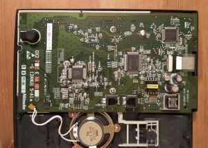
Three major ICs, the LCD connector, and the wonderful world of PSTN power supplies.

Let’s start at the top.

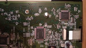
X2 is labelled Mitsubishi, M38003M6, and is by all accounts, a mask rom H8/300L series. Part numbers match up for Renesas (the current owner at least) I suspect this is handles all the programmable buttons and the LCD? X1 is a bit of a mystery, it’s labelled NEC D65825GF043. No idea what this is. Custom asic for phones? *shrugs*
Down to the bottom…

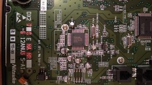
X3, Toshiba TC35324F. I found TC35300 and TC35310, both DTMF decoders. I suspect that this listens in on it’s own keypad? Seems a bit excessive though?

X7 (what happened to X4/X5/X6) Is a plain old MC34119. An audio amplifier. The fun things with old tech like this, it talks about being “low current” with only 2.7mA Iq, suitable for batteries :) The datasheet I found even excitedly mentions that it contains 45 active transistors! Whee.

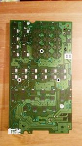
Finally, back side. Just keypads and LEDs really.

Anyway. There it is. Not really sure what next. It wouldn’t be completely unreasonable to just make a whole new pcb that fits under all the button pads, but that’s a lot more than I was planning on. JLPCB and elecrow will make pcbs that big for ~$10 each, but it’s a tedious button pad design. Could do a smaller PCB, only do some of the buttons, just for less hassle, but, meh. Could try and probe up some buttons, lay a big rats nest of wire down. Possibly the easiest way would be to desolder one of the ICs and put something in it’s place, a bunch of selective trace cutting, see if all the buttons go there? Or maybe just look for a different phone altogether…

Cypress CY8CKIT-049-42XX – PSoC 4200 kit – first impressions

(This was a draft I write in 2015, thought I might as well publish it where I’d left it)
Cool packaging, just like in the PSoC5LP kit. Despite looking similar, with a breakoff section that plugs into USB, the “programmer” side actually isn’t. It’s Cypress’s USB Serial bridge chip, the CY7C65211, and you program by using the UART bootloader on the PSoC 4200 target. Totally functional, totally valid. Not nearly as useful as a full debugger for application development of course, but in effect, it’s a full eval board for the usb serial chip. You can get a config tool that turns it into USB-SPI, USB-I2C, and USB-GPIO dongles. Neat, but still, I didn’t get this to evaluate usb serial bridge chips. On the bright side, it does at least detect properly out of the box as a serial UART in linux. (Unlike the KitProg on the PSoC5LP kit)

GVFS mount points, or, how to completely ignore usability while building a usability feature.

Gnome happily mounts my phone’s MTP shares for me. I can even browse for them in “files” and drag and drop and everything. It’s pretty cool. And, magically, behind the scenes, it even exists in the filesystem so I can use rsync and cp and things.

But the mount point…. Oh boy. What on earth were they thinking. /run/user/1000/gvfs/mtp\:host\=%5Busb%3A002%2C010%5D/
Are you fucking kidding me? That’s an url encoded way of saying [usb:002,010] Why did it need to be url encoded? No idea. What about the content? Oh, that’s the USB bus, and device address. Spectacular. That means it depends on not only what physical port it’s plugged into, but what order it was plugged in. (And that unplugging and replugging will make a new path) Let’s not use things like iManufacturer, iProduct, iSerial, vid, pid, anything actually device specific no, not here.

I’m sure this was done to try and ensure that the mount point would be unique. Great. Mission accomplished. However, it could be made unique, and usable at the same time. And then this thing, that exists out of a usability feature, would actually be more usable.

Netbeans 8.x “Could not get children iterator” or “NULL VALUE RETURNED FOR CHILDREN”

If you’re getting messages like this when debugging and trying to look at variables, chances are you might be debugging some glib2 code. If you are, welcome to https://bugzilla.gnome.org/show_bug.cgi?id=749092

It’s easy enough to manually patch the file, and presto, working debug again. It’s been fixed in GDB, I was seeing this in Fedora 22, which is not _entirely_ up to date these days, but you tend to expect that plain old host debugging should be pretty stable. blog post because the netbeans error string doesn’t help you find that gdb bug. You need to run gdb on the command line to find the real error: Python Exception iter() returned non-iterator of type '_iterator':

More arm android box conversion adventures

TL;DR: Still failing. Gave up again.

Back when I bought a RK3066 based device, I had seen rockchip developers start contributing directly upstream.  However, the RK3066 just missed the boat, and while I poked and prodded a bit, it was all just a bit too difficult and a bit too complicated a bit too much not much fun.  Still, I followed what was going on.  The plan was to use the swell of consumer electronics to get a cheap android tv box that I could run linux on, and use as a small home server.  “Just use a raspi” you say.  Well, no.  Raspi3 is at least decently powerful, but running everything off a sdcard, and not having a case is really not what I was looking for.  Little tiny cute black boxes, with a remote control and a power supply and ethernet and usb shipped for $30?  That’s what I want to reuse.  Rockchip continued to contribute upstream, so I bought a MXQ 4K (RK3229).  New hotness I thought, but the cheap end.  I still believed that rockchip was doing the best job of upstream support.  Note: My copy of this device has a much smaller heatsink, Spectek flash, not Sandisk, and some generic no name ram chips. (See pics)

Top side, smaller heatsink, no name ram.

Top side, smaller heatsink, no name ram.

Maybe they are.  And I’ve not worked on amlogic or sunxi chips, but goddamn, the work environment is still just as sucky.  A garbage world of “custom roms” and complicated documentation detailing multiple ways of doing things with rarely any explanation of why.  I’ve still no idea, but some things seem a little clearer than last time… maybe?

If you just want to run linux, in _theory_ you can just use the existing android kernel shipped stock.  It has support for all your hardware, you just need to replace the root file system (RFS) and amend the kernel command line to say where your rootfs is.  Except, because some of the drivers are actually separate binary proprietary modules, you end up needing a fucking initrd/initramfs timewaste so it can have such core details like a functional fucking nand driver.  Why the fuck rockchip is keeping _this_ bit proprietary is beyond me.  So that gets non-trivial quickly.  You can in theory extract the modules from your android system image.  If you have a stock firmware, (“update.img”) you can use rkunpack from the rkflashtool repository.  you’ll probably have to unpack more than once.  Documentation on what’s what is less than forthcoming.  The “system.img” wil be a raw ext4 image (in theory) and you can mount it locally to explore with “sudo mount -o loop blah.img somemountpoint”

anyway, while some of this is just for my own notes, not really for anyone else, one thing has stuck out.  First, the default serial console is at 1500000 baud.  Thanks for nothing rockchip.  On a cp2102 serial dongle, you’ll need to use the silabs baud rate aliasing software to get to this baud rate.  Thanks for nothing silabs. and yeah, again, thanks for nothing rockchip.  The serial console is in the picture below.

Bottom side, spectek flash, serial console details

Bottom side, spectek flash, serial console details

Oh yeah, the “thing that has stuck out”  Despite being “unbrickable” because they have a maskrom bootloader, and normally just going into recovery mode,  I’ve had great difficulty.  After some bad flashing,  (bad why? no idea, rkflashtool or upgrade_tool both successfully report the flashing complete, then I reboot, and get…. bad things) the serial console will hang on a line like…

In
300MHz
DDR3
Bus Width=32 Col=10 Bank=8 Row=15 CS=1 Die Bus-Width=16 Size=1024MB
mach:2
OUT
Boot1 Release Time: 2016-03-15, version: 2.31
ChipType = c 275
No.1 FLASH ID:2c 64 64 56 a5 4
ECC:60
ReadRetry pageadd=15d800  ecc=3c err=ffffffff
Read pageadd=15d800  ecc=3c err=ffffffff
spare: 0x0:b8679151 b8679151 b8679151 b8679151 
ReadRetry pageadd=15d801  ecc=3c err=ffffffff
Read pageadd=15d801  ecc=3c err=ffffffff
spare: 0x0:527ded0c 527ded0c 527ded0c 527ded0c 
SdmmcInit=0 20
StorageInit ok = 134644
SecureMode : SBOOT_MODE_NS
powerOn 812121
Usb re Boot. 6812118

At this point, rkflashtool v will “fail” like so… (notice mangled text)

$ rkflashtool v
rkflashtool: info: rkflashtool v5.2
rkflashtool: info: Detected RK322X...
rkflashtool: info: interface claimed
rkflashtool: info: chip version: 322A-��..��-��

upgrade_tool will still say the device is connected, in “Loader” mode, and TestDevice, ReadFlashID, ReadFlashInfo and ReadChipInfo all still work. But attempting to download any image will fail saying parameter is invalid. rkflashtool p agrees.

 rkflashtool p
rkflashtool: info: rkflashtool v5.2
rkflashtool: info: Detected RK322X...
rkflashtool: info: interface claimed
rkflashtool: info: reading parameters at offset 0x00000000
rkflashtool: info: size:  0x0000ffff
rkflashtool: fatal: Bad parameter length!

One time this happened, I got out of it by having the USB-A-A cable disconnected (oh yeah, A-A for OTG? thanks for fucking nothing rockchip, hooray port overloads and reverse powering disasters) holding the recovery button down (with a toothpick down the SPDIF hole. (button down the AV hole _should_ be different but seems to behave the same for me)) and then plugging in the main power supply. Perhaps it had been a problem with powering the device purely via the A-A cable as I’d normally been doing?

Who knows. It’s currently in this state again, the unbrickable “bricked” Even shorting pins 7-8 on the NAND chip itself and powering up isn’t helping. (The “standard” rockchip method of getting back to maskrom mode) I get a different log, but it’s still non-responsive, even after inserting the A-A cable. (Still in loader, but not really working)

DDR Version V1.04 20160504
In
300MHz
DDR3
Bus Width=32 Col=10 Bank=8 Row=15 CS=1 Die Bus-Width=16 Size=1024MB
mach:2
OUT
Boot1 Release Time: 2016-03-15, version: 2.31
ChipType = c 276
No.1 FLASH ID:2c 64 64 56 a5 4
FlashLoadPhyInfo fail 2bc!!
sync para 32
sync para 32
ECC:60
ReadRetry pageadd=15d800  ecc=3c err=ffffffff
Read pageadd=15d800  ecc=3c err=ffffffff
spare: 0x0:b8679151 b8679151 b8679151 b8679151 
ReadRetry pageadd=15d801  ecc=3c err=ffffffff
Read pageadd=15d801  ecc=3c err=ffffffff
spare: 0x0:527ded0c 527ded0c 527ded0c 527ded0c 
SdmmcInit=0 20
StorageInit ok = 93093
SecureMode : SBOOT_MODE_NS
powerOn 770567
Usb re Boot. 6770565

So. No results, no future, but at least a weird log for the internet to archive if it helps anyone sometime.