Category Archives: sensor networks

Home Assistant Matter Server with Podman

Yet more updates, turns out as of a few days ago, they now actually provide a container of the matter server _without_ all the home assistant OS cruft. so it’s even easier:

$ podman run -v /etc/localtime:/etc/localtime:ro -v /run/dbus:/run/dbus:ro  -d --network=host ghcr.io/home-assistant-libs/python-matter-server:stable

(Original below)

so, home assistant only formally supports matter via an home assistant “Addons” which are only supported by the Home Assistant “OS”. That’s… not a cool way of runnings for me, and all it really does is run a docker server wrapping an external service they made, python-matter-server

The Docker service they made is here: https://github.com/home-assistant/addons/tree/master/matter_server This… doesn’t run nicely with podman, but it can mostly be worked around pretty easily.

So, assuming you have home assistant already running on localhost, under podman:

$ podman run -v /etc/localtime:/etc/localtime:ro -v /run/dbus:/run/dbus:ro  -d --network=host -e SUPERVISOR_API=http://localhost docker.io/homeassistant/aarch64-addon-matter-server:latest

The -e SUPERVISOR_API call doesn’t actually do anything, because you don’t actually have the home assistant supervisor, but it might be helpful in some cases, and shows you how to do it anyway.

Originally there were more instructions, below, but they actually went and fixed my bug report eventually, so you no longer need anything other then “usual” podman invocations on their default image.


Unfortunately you will need to edit a few layers, as they seem pretty against letting this be run easily without their entire OS

# First make sure we're up to date
$ podman pull docker.io/homeassistant/aarch64-addon-matter-server
# now, run that, and get a shell in it, we need to edit...
$ podman run -d docker.io/homeassistant/aarch64-addon-matter-server
390841611cf49675741ec72ea91341aef628fd6865bba51eeee9d0f1533473b8
$ podman exec -it -l /bin/bash
root@390841611cf4:~#

Ok, now, what are we fixing? Well, the log line from that bug report linked first… Despite closing my issue, they actually fixed this later…

That… actually means you don’t need to do any image fuckery at all… Lets just do some magic podman to replicate the docker file sufficiently…

Xiaomi Miijia LYWSD03MMC with pure bluetoothctl

Because software is software, it all gets thrown out every now and again for….. reasons. BlueZ, on linux, has moved away from hciconfig and hcitool and gattttool and so on, and it’s all “bluetoothctl” and “btmgmt” See https://wiki.archlinux.org/title/Bluetooth#Deprecated_BlueZ_tools for some more on that.

Anyway, I got some of these really cheap Xiaomi BTLE temperature+humidity meters. Turns out there’s a custom firmware you can flash to them and all sorts, but really, I was just interested in some basic usage, and also, as I’m getting my toes wet in bluetooth development, working out how to just plain use them as intended! (well, mostly, I’ve no intention of using any Xiaomi cloud apps)

This application claims to use the standard interface, and it’s “documentation” of this interface is https://github.com/JsBergbau/MiTemperature2#more-info and the little bit of code at

def connect():
	#print("Interface: " + str(args.interface))
	p = btle.Peripheral(adress,iface=args.interface)	
	val=b'\x01\x00'
	p.writeCharacteristic(0x0038,val,True) #enable notifications of Temperature, Humidity and Battery voltage
	p.writeCharacteristic(0x0046,b'\xf4\x01\x00',True)
	p.withDelegate(MyDelegate("abc"))
	return p

Well, that wasn’t very helpful. Using tools like NrfConnect, I’m expecting things like a service UUID and a characteristic UUID and things. Also, I don’t have gatttool to even try it like this :)

So, how to do it in “modern” bluetoothctl? Here’s the cheatsheet. First, find our meters…

$ bluetoothctl
# menu scan
# clear
# transport le
# back
# scan on
SetDiscoveryFilter success
Discovery started
[CHG] Controller <your hci mac> Discovering: yes
[NEW] Device <a meter mac> LYWSD03MMC
[NEW] Device <other devices> <other ids>
# scan off

Now, we need to connect to it. According to https://github.com/custom-components/ble_monitor#supported-sensors it actually does broadcast the details about once every 10 minutes, which is neat, but you need a key for it, and aintnobodygottimeforthat.gif.

# connect <mac address>
lots and lots of spam like
[NEW] Descriptor (Handle 0x9f94)
	/org/bluez/hci0/dev_MAC_ADDRESS/service0060/char0061/desc0063
	00002901-0000-1000-8000-00805f9b34fb
	Characteristic User Description
[NEW] Descriptor (Handle 0xa434)
	/org/bluez/hci0/dev_MAC_ADDRESS/service0060/char0061/desc0064
	00002902-0000-1000-8000-00805f9b34fb
	Client Characteristic Configuration
[NEW] Characteristic (Handle 0xa904)
	/org/bluez/hci0/dev_MAC_ADDRESS/service0060/char0065
	00000102-0065-6c62-2e74-6f696d2e696d
	Vendor specific
[NEW] Descriptor (Handle 0xb1d4)
	/org/bluez/hci0/dev_MAC_ADDRESS/service0060/char0065/desc0067
	00002901-0000-1000-8000-00805f9b34fb
	Characteristic User Description
....more lines like this.
[CHG] Device MAC_ADDRESS UUIDs: 00000100-0065-6c62-2e74-6f696d2e696d
[CHG] Device MAC_ADDRESS UUIDs: 00001800-0000-1000-8000-00805f9b34fb
[CHG] Device MAC_ADDRESS UUIDs: 00001801-0000-1000-8000-00805f9b34fb
[CHG] Device MAC_ADDRESS UUIDs: 0000180a-0000-1000-8000-00805f9b34fb
[CHG] Device MAC_ADDRESS UUIDs: 0000180f-0000-1000-8000-00805f9b34fb
[CHG] Device MAC_ADDRESS UUIDs: 0000fe95-0000-1000-8000-00805f9b34fb
[CHG] Device MAC_ADDRESS UUIDs: 00010203-0405-0607-0809-0a0b0c0d1912
[CHG] Device MAC_ADDRESS UUIDs: ebe0ccb0-7a0a-4b0c-8a1a-6ff2997da3a6
[CHG] Device MAC_ADDRESS ServicesResolved: yes

The characteristic you need is ebe0ccc1-7a0a-4b0c-8a1a-6ff2997da3a6, under the similar service UUID. So now, we just “subscribe” to notifications from it.

# menu gatt
[LYWSD03MMC]# select-attribute ebe0ccc1-7a0a-4b0c-8a1a-6ff2997da3a6
[LYWSD03MMC:/service0021/char0035]# notify on
[CHG] Attribute /org/bluez/hci0/dev_MAC_ADDRESS/service0021/char0035 Notifying: yes
Notify started
[CHG] Attribute /org/bluez/hci0/dev_MAC_ADDRESS/service0021/char0035 Value:
  36 09 2a f6 0b                                   6.*..           
[CHG] Attribute /org/bluez/hci0/dev_MAC_ADDRRESS/service0021/char0035 Value:
  35 09 2a f6 0b                                   5.*..           
[CHG] Attribute /org/bluez/hci0/dev_MAC_ADDRESS/service0021/char0035 Value:
  33 09 2a f6 0b                                   3.*..           
[LYWSD03MMC:/service0021/char0035]# notify off

And…. now we can go back to https://github.com/JsBergbau/MiTemperature2#more-info and decode these readings.

>>> x = "2a 09 2a 4e 0c"
>>> struct.unpack("<HbH",binascii.unhexlify((x).replace(" ","")))
(2346, 42, 3150)

With Python, that gives us a temperature of 23.46°C, humidity of 42%, and a battery level of 3.150V.

Yay.


Originally, I was blind to the subtle differences in the characteristic UUIDs, and thought I had to hand iterate them. The below text at least shows how you can do that, but it’s unnecessary.

Ok, now the nasty bit. We want to get notifications from one of the characteristics on service UUID ebe0ccb0-7a0a-4b0c-8a1a-6ff2997da3a6. But you can’t just “select” this, because, at least as far as I can tell, there’s no way of saying _which_ descriptor you want.

So, first you need to use scroll that big dump of descriptors (or view it again with list-attributes in the gatt menu) to work out the “locally assigned service handle” In my case it’s 0021, but I’ve got zero faith that’s a stable number. You figure it from a line like this…

[NEW] Characteristic (Handle 0xd944)
	/org/bluez/hci0/dev_MAC_ADDRESS/service0021/char0048
	ebe0ccd9-7a0a-4b0c-8a1a-6ff2997da3a6
	Vendor specific

Now, which characteristic is which? Well, thankfully, Xiaomi uses the lovely Characteristic User Description in their descriptors, so you just go through them one by one, “read”ing them, until you get to the right one…

[LYWSD03MMC:]# select-attribute /org/bluez/hci0/dev_MAC_ADDRESS/service0021/char0035/desc0037 
[LYWSD03MMC:/service0021/char0035/desc0037]# read
Attempting to read /org/bluez/hci0/dev_MAC_ADDRESS/service0021/char0035/desc0037
[CHG] Attribute /org/bluez/hci0/dev_MAC_ADDRESS/service0021/char0035/desc0037 Value:
  54 65 6d 70 65 72 61 74 75 72 65 20 61 6e 64 20  Temperature and 
  48 75 6d 69 64 69 74 79 00                       Humidity.       
  54 65 6d 70 65 72 61 74 75 72 65 20 61 6e 64 20  Temperature and 
  48 75 6d 69 64 69 74 79 00                       Humidity.       
[LYWSD03MMC:/service0021/char0035/desc0037]#

The sucky bit, is you need to manually select _each_ of the “descNNNN” underneath _each_ of the “charNNNN” under this service. (On my devices, it’s the second characteristic with dual descriptors…)

now, select the characteristic itself. (you can’t get notifications on the descriptor…)

[LYWSD03MMC:/service0021/char0035/desc0037]# select-attribute /org/bluez/hci0/dev_MAC_ADDRESS/service0021/char0035
[LYWSD03MMC:/service0021/char0035]# notify on
[CHG] Attribute /org/bluez/hci0/dev_MAC_ADDRESS/service0021/char0035 Notifying: yes
Notify started
[CHG] Attribute /org/bluez/hci0/dev_MAC_ADDRESS/service0021/char0035 Value:
  2b 09 2a 4e 0c                                   +.*N.           
[CHG] Attribute /org/bluez/hci0/dev_MAC_ADDRESS/service0021/char0035 Value:
  2a 09 2a 4e 0c                                   *.*N.           
[CHG] Attribute /org/bluez/hci0/dev_MAC_ADDRESS/service0021/char0035 Value:
  2b 09 2a 4e 0c                                   +.*N.           
[CHG] Attribute /org/bluez/hci0/dev_MAC_ADDRESS/service0021/char0035 Value:
  2b 09 2a 4e 0c                                   +.*N.           
[CHG] Attribute /org/bluez/hci0/dev_MAC_ADDRESS/service0021/char0035 Value:
  29 09 2a 4e 0c                                   ).*N.           
[LYWSD03MMC:/service0021/char0035]# notify off
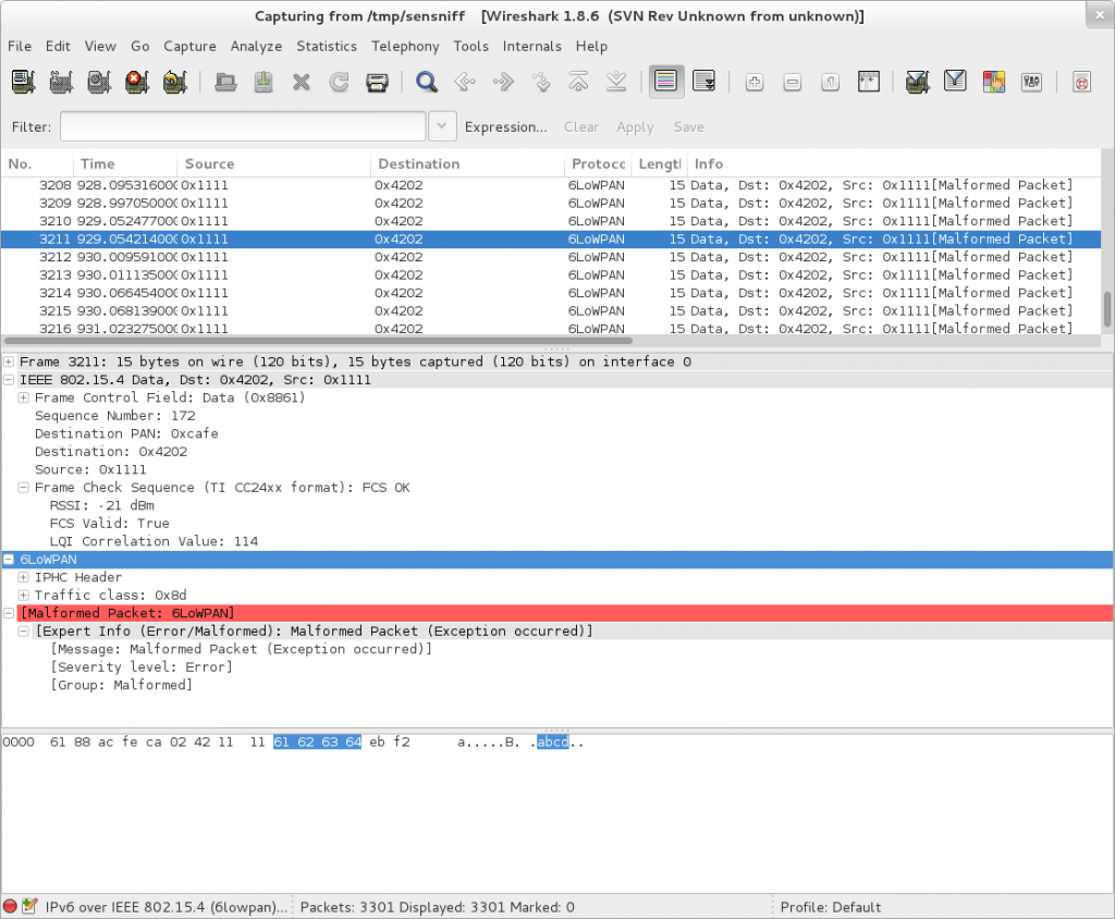
Sniffing 802.15.4 with wireshark and MRF24J40 modules

Wireshark screenshot showing my test data

This is what I did the last two evenings or so. The data being sent is from my example app for my MRF24J40 module library, simrf.

The streaming into wireshark is all thanks to one of the Contiki devs, George Oikonomou’s sensniff project. The peripheral code is just another app using my library.

Neat! This should make some things a bit easier to understand as I move into getting the full networking stack working in Contiki. (You can ignore the warnings from wireshark about the packets being invalid 6LoWPAN frames, all the frames are just raw 802.15.4, with “abcd” being sent as the frame payload.

Further adventures with Contiki OS

I got the (very) basic things working with my port of Contiki OS to my stm32l discovery and stm32vl discovery boards. It was more painful than I expected, there were some unexpected things, but generally, nothing too complicated. Now, I’m at the point where I was hoping to be, starting to try and use the networking stacks in Contiki OS. I want to use the 6LoWPAN implementation, the RPL implementation, the TCP (v4 and v6) implementations.

And here things unravel very quickly. The docs had lead me to believe that I just needed to implement “rtimers” and it would all start working. Turned out the docs referred to an API 5 years out of date. rtimers only actually support a single timer, so you can’t really actually use them in your own apps, you’re really just providing them for the exclusive use of the radio duty cycling (RDC) code. Of which there are multiple styles.

So, yeah, you don’t need to implement them at all. Think of them as rdc_timer and it all makes a lot more sense. They were presumably only introduced at all as the existing timer code (etimer/ctimer) are based on co-operative multi tasking, and RDC algorithms need relatively hard timing to do the radio strobing.

So, what’s the status of Contiki then? The mailing list gives an interesting picture. You’ve got some very advanced topics being discussed about packet loss modelling and distance calculation methods and tweaking the latest draft of CoAP implementation. Then you’ve got posts about simple things that still aren’t fixed like examples simply not even compiling.

Oh yeah, that’s right, did I mention that? There’s examples that don’t compile. You can apply some “fixes” to make them compile, but they’re clearly not the way the makefiles and the project were intended to be, and no-one who might know is
answering.

Stepping out again, it starts to feel like Contiki OS isn’t really an OS project that you can use as is. It’s an OS that’s an incubator for other projects. TCP and UDP for both ipv4 and v6, with all of it configurable via an undocumented mix of makefile variables and C preprocessor defines. A windowing toolkit, because why wouldn’t I want to VNC to my battery powered wireless sensor node and click on things. (I’m serious, the current tree includes a graphical calculator app and a vnc server) Three different RDC algorithms. Two different CoAP implementations. A rather large and complex java modelling framework. Two different file systems. Two different webservers and a webbrowser. This is all in the same tree, along with support for ~20 platforms with ~6-7 different architectures.

It starts to make a bit more sense when you realise that it all started out as an operating system for a commodore 64, but that doesn’t really excuse it per se. Shit’s broken. Shit aint improving real fast. Back to the two different sorts of threads on the mailing list and it starts making more sense again. There’s the CS research types, using hardware the previous grad student used, with the magic incantations from the previous researcher, working on really interesting science, and Contiki OS is the base. Then there’s people who are looking around for some modern networking stacks to use on a device of their own. These other people currently have a pretty raw deal. It’s like the Contiki itself really, some really neat cutting edge science, with sharks and hot burning sun and no water nor a soul in sight to ask for help.

Fortunately, there does appear to be a few birds in the sky, hinting at land. Contiki OS’s now a github project, and getting actual pulls, rather than just being hidden inside a Swedish University. There’s a bunch of people who seem keen to try and clean up some of the accumulated cruft of ten years of grad projects being dumped into a repository somewhere. Now if only there was a little bit of direction and documentation from central leaders and we could really sail!

Running Contiki examples on your linux system

Contiki has a bunch of examples, and most of it can be compiled to run on your local system, “native” and also in a special platform called “minimal-net”

So, let’s go and try and build one, say, [contiki-root]/examples/webserver That should be nice and easy.

contiki-minimal-net.a(contiki-main.o): In function `main':
/home/karlp/src/contiki-locm3/examples/webserver/../../platform/minimal-net/./contiki-main.c:298: undefined reference to `uip_ds6_if'
/home/karlp/src/contiki-locm3/examples/webserver/../../platform/minimal-net/./contiki-main.c:304: undefined reference to `uip_ds6_if'
contiki-minimal-net.a(tcpip.o): In function `tcpip_input':
/home/karlp/src/contiki-locm3/examples/webserver/../../core/net/tcpip.c:532: undefined reference to `uip_ext_len'
contiki-minimal-net.a(tcpip.o): In function `tcpip_ipv6_output':
/home/karlp/src/contiki-locm3/examples/webserver/../../core/net/tcpip.c:562: undefined reference to `uip_ds6_is_addr_onlink'
/home/karlp/src/contiki-locm3/examples/webserver/../../core/net/tcpip.c:566: undefined reference to `uip_ds6_route_lookup'
/home/karlp/src/contiki-locm3/examples/webserver/../../core/net/tcpip.c:568: undefined reference to `uip_ds6_defrt_choose'
/home/karlp/src/contiki-locm3/examples/webserver/../../core/net/tcpip.c:597: undefined reference to `rpl_update_header_final'
/home/karlp/src/contiki-locm3/examples/webserver/../../core/net/tcpip.c:602: undefined reference to `uip_ds6_nbr_lookup'
/home/karlp/src/contiki-locm3/examples/webserver/../../core/net/tcpip.c:603: undefined reference to `uip_ds6_nbr_add'
/home/karlp/src/contiki-locm3/examples/webserver/../../core/net/tcpip.c:620: undefined reference to `uip_ds6_addr_lookup'
/home/karlp/src/contiki-locm3/examples/webserver/../../core/net/tcpip.c:621: undefined reference to `uip_nd6_ns_output'
/home/karlp/src/contiki-locm3/examples/webserver/../../core/net/tcpip.c:623: undefined reference to `uip_nd6_ns_output'
/home/karlp/src/contiki-locm3/examples/webserver/../../core/net/tcpip.c:626: undefined reference to `uip_ds6_if'
/home/karlp/src/contiki-locm3/examples/webserver/../../core/net/tcpip.c:677: undefined reference to `uip_ext_len'
contiki-minimal-net.a(tcpip.o): In function `process_thread_tcpip_process':
/home/karlp/src/contiki-locm3/examples/webserver/../../core/net/tcpip.c:769: undefined reference to `rpl_init'
contiki-minimal-net.a(tcpip.o): In function `eventhandler':
/home/karlp/src/contiki-locm3/examples/webserver/../../core/net/tcpip.c:479: undefined reference to `uip_ds6_timer_periodic'
/home/karlp/src/contiki-locm3/examples/webserver/../../core/net/tcpip.c:480: undefined reference to `uip_ds6_timer_periodic'
/home/karlp/src/contiki-locm3/examples/webserver/../../core/net/tcpip.c:481: undefined reference to `uip_ds6_periodic'
collect2: error: ld returned 1 exit status
make: *** [webserver-example.minimal-net] Error 1

Oops. In commit 2d50a406 IPv6 was turned on by default, but the minimal-net platform doesn’t seem to support ipv6 (yet) I fully believe this to be a short term problem, but it’s extremely disheartening when you see it straight away.

So, to work around this, you can edit [contiki-root]/core/contiki-default-conf.h. About line 100, comment out the line #define UIP_CONF_IPV6 1. (I would not have found this myself, but one of the users of #contiki-os helped me out)

Ok, so you build. And you run. And… it fails again.

~/src/contiki-locm3/examples/webserver $ ./webserver-example.minimal-net 
RPL enabled
ioctl(TUNSETIFF): Operation not permitted
~/src/contiki-locm3/examples/webserver $

This time, it’s because the minimal-net platform actually makes some tricks. It tries to create and set up a tun/tap interface, creating a virtual network cable to your application. Remember, your application is a complete operating system with a full networking stack. But regular users can go doing that sort of thing, so… let’s run it with sudo…

~/src/contiki-locm3/examples/webserver $ sudo ./webserver-example.minimal-net 
[sudo] password for karlp: 
RPL enabled
ifconfig tap0 inet 172.18.0.1/16
route add -net 172.18.0.0/16 dev tap0
IP Address:  172.18.0.2
Subnet Mask: 255.255.0.0
Def. Router: 172.18.0.1

*******Contiki-2.6-487-g96e85cc online*******

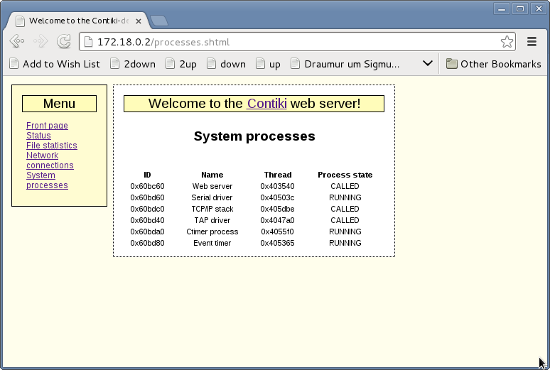
Cool! That looks better! I can ping 172.18.0.2, and ifconfig shows me this virtual network. (At this point nmap should be able to fingerprint the OS (according to the contiki docs) but it totally fails for me at least.) Anyway, we built a webserver! Let’s check it out!

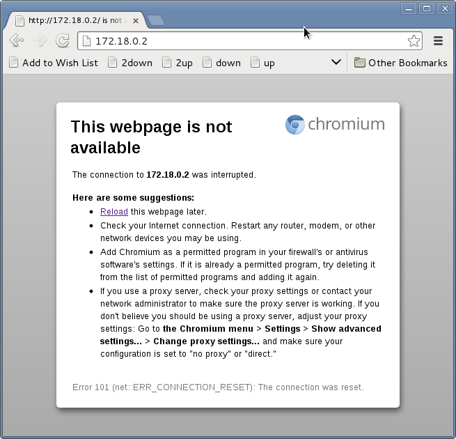
So that failed hard. Curl/wget doesn’t work either. And there was nothing on the console log, even after turning on logging. (A story in it’s own right, why would that not be on by default for the example running on the native host?)

I went down a rabbit hole here trying to work out what was going on. I got into gdb and could see action when I made a webrequest, but couldn’t follow the code well enough through Contiki’s protothreads to see what happened next. Still suspecting some ipv6 difficulties, I went and had a look through the [contiki-root]/core/contiki-default-conf.h file again. And found this gem…

/* UIP_CONF_BUFFER_SIZE specifies how much memory should be reserved
   for the uIP packet buffer. This sets an upper bound on the largest
   IP packet that can be received by the system. */
#ifndef UIP_CONF_BUFFER_SIZE
#define UIP_CONF_BUFFER_SIZE 128
#endif /* UIP_CONF_BUFFER_SIZE */

Now, that’s pretty small. It doesn’t say what happens when it gets a bigger packet, but I’m guessing it’s not pretty, and from the behaviour, it’s probably just terminating the connection if it runs out of buffer space. (“The connection was interrupted” in chrome and “* Recv failure: Connection reset by peer” from curl)

Ok, let’s change that to something bigger, 512 for starters. And…..

We’re finally working! Whee!

It turns out, you can get this to respond properly from curl by setting the useragent to something much smaller, but that’s not really all that helpful is it? So, in my mind, this is something that needs to be updated for contiki for the minimal-net platform. It’s totally reasonable to have a limit on the IP packet size for the final sensor nodes, when you know what you’re doing, but the example code, which is meant to run on your host system by default, using the minimal-net platform, should just work!. I’m trying to work up a clean pull request for this. (I can’t seem to get “project-conf.h” based overrides to work, and it’s late, so it will be another day)

Porting Contiki on STM32 (libopencm3) continued – timers and clocks and uarts

When I fixed my stupid error earlier, I got stdout/printf working. I then poked a lot of simple examples and started to understand how to write simple contiki apps using protothreads. It’s really pretty simple, as long as you remember that it’s all done with switch/case magic, so you can’t use stack variables the way you might expect. This is ok. This makes you think more about where you data lives and what you’re passing around. With stdout working though, I started to go through what else was needed.

Contiki offers ~4 different apis for doing things at some point in time. ctimers, etimers, stimers and rtimers. (And also with the clock_* api, which are for when you reallllllly want to do some busy waiting. Don’t do that!) This wiki page was very helpful in understanding the differences, and even having some “porting guide” information. This is an area I feel contiki is very weak in, the almost complete lack (to my eyes) of a porting guide. There’s quite a few different ports in the tree, but they’re often implemented in quite radically different ways, and some of them appear to be unmaintained.

But, the good thing about all these timers, is that’s all core. Your port only needs to implement clock.c, and it’s basically all taken care of! Neat! Except rtimers. rtimers are the realtime timers, used for turning radios on and off at the right times to synchronize. When I get to the radio (soon) I’ll be looking at other implementations and seeing what’s best.

As it stands though, ctimers, etimers, timers and the clock routines are all working in my port, and I’d played with some simple play applications to test out how they worked. I then tried to get the shell working. So, this is an app. So you need to put APPS+=serial-shell into your makefile. (Remember, this is the makefile for your final application) Then, because the AUTOSTART_PROCESSES() macro can only be used once in an application, the apps you can include can’t use that macro. You need to start them yourself. Here’s what my “demo” playground main application process looked like:

PROCESS_THREAD(foo_process, ev, data)
{
  PROCESS_BEGIN();
 
  printf("Hello foo world\n");
  leds_blink();  // oh yeah, the leds api works for the stm32l discovery board too ;)
  serial_shell_init();  // starts the serial shell process
 
  // these are all commands the shell can run.  
  shell_ps_init();
  shell_blink_init();
  shell_powertrace_init();
 
  // these are experiments with my own applications
  static struct blipper_info bl1 = { CLOCK_SECOND * 2, 'a' };
  static struct blipper_info bl2 = { CLOCK_SECOND * 5, 'b' };
  process_start(&blipper_process, (void*)&bl1);
  process_start(&blipper2_process, (void*)&bl2);
 
  PROCESS_END();
}

Note that serial-shell is actually just a wrapper around the shell app.
Note that you need to call a shell_XXXXX routine for each command you need to add. Note well that that is not documented anywhere. You actually have to look in [contiki-root]/apps/shell for all the shell-xxx.c files that call shell_register_command() Or, have a look at [contiki-root]/examples/example-shell/example-shell.c

Ok, so you got a shell application built and flashed. But… it doesn’t work! I ran into two problems here. One of them was very well documented, I just didn’t read it. I was used to having to implement newlib syscalls like _read() and _write(), but you actually need to not implement _read(), and make sure you just follow the directions!.

Unfortunately, in my case, this wasn’t enough. I could run my application with the native target, but not on my stm32. Again, reading the documentation, contiki processes serial input line by line, looking for a line feed (hex 0xa) to mark the end of line, and completely ignoring carriage return characters (hex 0xd) With gdb I could see that on the native platform, entering a command and pressing “enter” sent only a LF character, and it worked. With picocom and a USB-serial adapter to my board, I was seeing only a CR character, which was ignored. Wikipedia has a lot to say about this, and some of the helpful people on ##stm32 pointed out that this was because my serial device was in “cooked” mode, and I could put it back to raw mode to send the “right” characters. Turns out lots of terminal software has to deal with this, and miniterm.py (Something I just happened to have installed anyway) by default does the “right thing” (or the other thing) There were some suggestions that contiki should probably be more flexible in it’s input, and deal with both either, or, and both, but not require a specific one. That’s a future debate, but not one I’m battling now.

With a different serial terminal program, all of a sudden I had a console, and a shell. Here’s a full log of my app running, and me typing, “ps” and “help”

--- Miniterm on /dev/ttyUSB2: 115200,8,N,1 ---
--- Quit: Ctrl+]  |  Menu: Ctrl+T | Help: Ctrl+T followed by Ctrl+H ---
Platform init complete
Hello foo world
Hello blipper id: a!
Started timer
Hello blipper2 id: b!
Started timer
Should get printed after any event, even if it wasn't ours....
callback about to be set...
Should get printed after any event, even if it wasn't ours....
0.0: Contiki> 
Should get printed after any event, even if it wasn't ours....
Processes:
ps
periodic blipper2 process
periodic blipper process
Shell server
Shell
Contiki serial shell
Ctimer process
Event timer
Serial driver
Should get printed after any event, even if it wasn't ours....
0.0: Contiki> 
a hit timer expiry tick: 0 at clock time: 2
Should get printed after any event, even if it wasn't ours....
In the callback!
Should get printed after any event, even if it wasn't ours....
Available commands:
?: shows this help
blink [num]: blink LEDs ([num] times)
exit: exit shell
help: shows this help
kill : stop a specific command
killall: stop all running commands
null: discard input
powertrace [interval]: turn powertracing on or off, with reporting interval 
ps: list all running processes
quit: exit shell
Should get printed after any event, even if it wasn't ours....
0.0: Contiki> 
a hit timer expiry tick: 1 at clock time: 4
Should get printed after any event, even if it wasn't ours....
b hit timer expiry tick: 0 at clock time: 5
b Should only print after our event....

--- exit ---

Note that there is no local echo of commands! (Again, this can be turned on by the terminal program, but often it’s handled by the far side’s shell implementation)

But, all’s well that ends well. At this point I have what’s a pretty complete port of the core of contiki to the STM32L discovery board, and all the code that is common for any stm32 (and mostly, any chip using libopencm3) is in the cpu section of contiki, rather than the platform code.

Now, it’s just time to start the radio drivers, and work out the best way of implementing the rtimers!

My Platform port: https://github.com/karlp/contiki-outoftree This is all you need to target the STM32L discovery, it includes my changes to Contiki, as well as libopencm3 as git submodules.
Contiki port: https://github.com/karlp/contiki-locm3/tree/locm3 You’ll need this if you want to make another platform port based on libopencm3

Fridge Controller – temperature and motor run time, reporting over 802.15.4

One of my most finished projects, mostly because it’s simply much more important than having a battery powered thermometer sitting on a shelf. I brew beer, and serve beer in a converted fridge in my loungeroom. One day, the beer got slow, and what came out was suspicously cold. Turns out the thermostat was broken, so as long as the fridge had power, it was cooling, which resulted in deeply frozen kegs of beer.

It’s a pretty old fridge, that I got free, so I thought about simply getting a new (second hand) fridge and doing the conversion again. A newer fridge would probably be quieter, use less energy, all good things. But, not all fridges are the same shape, and finding one that fit three kegs, and doing all the work of the conversion again just felt like a lot of work. And goddamnit, I’ve been building sensor nodes, I always planned on having nodes that could control things too, so maybe I should just get down to business.

In the end there wasn’t much too it. I’m not doing any fancy PID control, just a set point, and a minimum motor run time, and minimum motor rest time. Initially, it didn’t even listen to any controls from my network, it reported temperature and motor status, but that was it. I had no beer! This was too important to have offline for weeks while I played around 24-480

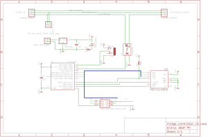
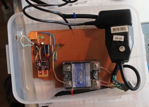
I got a (massivly overspecced) 25A SSR on ebay, and after a bit of thought about how to keep the cost down, came up with the following schematic:

Full schematic for the fridge controller

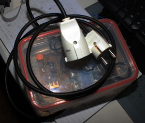
The clever bit, if I can call it that, was to not even think about making my own power supply for the control logic. Big companies can make 10 gazillion CE marked, compact, safe switch mode power supplies, and consumers can throw them out by the gazillion. I was just going to have a normal euro 2 prong socket, and a surplus phone charger plug pack with the jack cut off and soldered to the board. Presto, cheap _and_ safe. Far far cheaper, faster and easier than I could have done myself. Of course, the extra socket and jacks take up space, but you can only have so much cake.

There’s really not an awful lot more to it than that. I tested this with a teensy board first, because I could use the nice friendly USB port for debugging, then switched to the ATtiny84, and after a bit of fiddling to get USI working for SPI, it all “just worked” I was suitably impressed when the fridge turned on and off at the right times :)

If you want to make this cheaper, you can just drop the 802.15.4 radio altogether. It worked well enough to keep my beer cold but not frozen before I finished the code to listen for new parameters over the air. But, being able to tweak it’s settings is a nice thing.

The TMP36, or similar, is wired up on a chopped up length of headphone cable. This is the bit that’s easiest to get wrong. Take care with the pinouts of whatever headphone socket you use, and the way you wire which lead to which part of the 3.5mm stereo plug. (If you get it wrong, you’ll read temperatures like 50, then 80, then 90 degrees Celsius, which will actually be _correct_ if you touch the sensor!)

Things I would have liked to have done:

  • Make the headphone socket mount flush on the wall of the box. Just takes more money and time to get the mounting perfect.
  • Use a panel mount socket for both input and output. It would be much tidier, but it takes yet more space, and yet again, more money

Other notes

The SSR I got really needs 3V+ to control. I was mistakenly feeding it with about 2V, from the wrong side of a resistor divider, early on in testing, and the red LED on the device would light up, so I expected it to properly be switching the live side. However, it seems 2V was enough for the LED, but not enough to actually switch. As soon as I gave it 3V, it behaved perfectly.

There’s no LCD display. Which might have been nice, but really, how often do you look at the temperature of your fridge? Besides, because it’s reporting every 10 seconds to “karlnet” it becomes just another node that the rest of my system stores in databases, graphs, or uploads to pachube

The software has a fairly nice way of working with saved state in EEPROM I learnt recently. I’m quite happy with it :) However, in general, the code is a little bit harder to read, because it contains all the debug for a teensy board, with #defines separating the live code from the test code. This is however a fully fledged real demo of my updated MRF24J40 library code

Downloads

Parts list below.

Part

quantity

price

supplier

25A SSR, 3-25V control, 24-480VAC output

1

7.99 US

ebay

grounded euro socket

1

195 ISK

Byko

grounded euro plug

1

195 ISK

Byko

Ungrounded euro socket

1

181 ISK

Byko

3 strand power cable

2m

363 ISK

Byko

lunch box

1

499 ISK

Húsasmiðjan

Green LED

1

0.05€

Mouser

ATtiny84

1

2.39€

Mouser

MRF24J40MA

1 (optional)

7.46€

Mouser

3.5mm stereo socket, board mount

1

0.44€

Mouser

MCP1702, 3.3V regulator

1

0.39€€

Mouser

TMP36

1

1.58 US

Digikey

1uF capacitors

2

0.40€

Mouser

5V DC plugpack/wallwart

1

500 ISK

Second hand store

2×3 pin header for AVR programming

1

sockets and header pins to comfort

?

?

?

The mouser parts should be available as Shared project 3411228a84 You can substitute something else for the TMP36, that’s just what I had wired up.

Because remember, Digikey are evil, and still refuse to recognise that the 802.15.4 encryption was removed from export restrictions years ago. Digikey, in their infinite wisdom REFUSE TO SHIP 802.15.4 modules to Iceland. We’re terrorists or something.

Dresden Elektronik ATmega128RFA1 breakout boards, deRFmega128

I’ll write up more about the parts themselves later, but I finally got boards made for Dresden Elektronik’s deRFmega128 modules, both made, and now assembled and tested. Briefly, these are a module with Atmel’s ATmega128RFA1 (a combined ATmega128 with a 802.15.4 2.4 Ghz transceiver on a single chip) with either a chip antenna, or a connector for your own antenna. These are TINY, and they also manage to pack a 1Mbit EEPROM on the module, for your own use. All for 21€

I’ve only tested a basic blinky thing so far, but it’s good to know that I can finally start doing something with these cool modules.

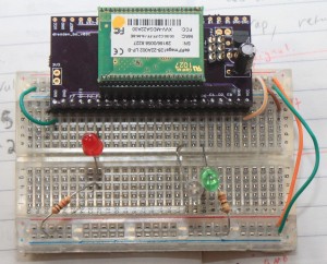
Here’s one up on a breadboard.

These modules are the same length as PJRC’s Teensy boards, but they have leads on 1.27mm pitch, not 2.54mm pitch. Lots more pins, but you’ll need some parts. For the 1.27mm socket holders, I ordered direct from Samtec. [1] Dresden recommends SLM Series, but I ordered SMS series. It may have been price, or availability, who knows. I ordered SMS-123-02-G-S, and the pins are really way too long on those. SMS-01-G-S would have been a better choice. Also, and I don’t know if the SLM would have been better, but I have a little bit of a hard time getting the modules into these sockets. They seem to “spring” out a little bit, to point that I initially thought I had failed to make my pcbs properly. Some of the pins weren’t making good contact. I have my modules mounted “upside down” with the silver RF can facing down. That’s the way the module leads are longest, and gold, and the only way they fit, when I was testing out the sockets and the modules. (Before the boards got here)

I’ve now found, that they will fit in nicely with the metal can UP and click into place nicely, but that’s not pin compatible with the AVR ISP header, or the power supply I put on the breakout.

So, I have some breakouts that work just fine, if you solder the part in, and probably well enough for development before your own boards, but I’m probably going to respin them :( The modules are cool, and they just came out with a pin compatible module, with an ARM7 core, instead of the ATmega128.

I still have a spare board from this revision though, if you are at all interested, I can send you one :)

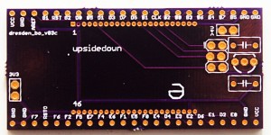
Here’s the board itself

Note, it already says rev3. That’s a story for another day :)

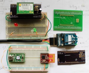
And to leave you, a picture of the different RF modules I’ve been working with here recently.

deRFmega128, Teensy v2 + MRF24J40MA, Xbee Series 1 + adafruit board

The current board files are available from https://github.com/karlp/karlnet/tree/master/experiments/dresden

The very basic blinking demo is also at github, should you really want it :)

[1] You can pretty much forget about getting 23pin headers from either digikey or mouser. Samtec were prompt, and had cheap enough shipping, relatively speaking. (I ordered a dozen)

3.3v from 2xAAs, switching regulators, learning surface mount

I’ve been running a couple of sensor nodes here on hacked together breadboards, with old camera batteries, telephone cable and string, but recently decided it was time to make some of these designs a little bit more permanent. So it was into CAD land, making the first PCBs I’ve had made since I left university. But one thing that I’ve been wanting, is a better power supply. Yes, 3.3V low dropout regulators, like the MCP1702, are cheap and easy and reliable. But, you really need at least 3xAAs. And in my mind, 3xAAs is just awkward. 4xAAs is less awkward, but you’re starting to talk about serious heft there, and besides, with a bit of care, 2xAAs should last a year or so, so 4 is just ridiculous.

But, I still wanted it to be cheap. Switching regulators have been around for ages, in various shapes and sizes, but they normally involve inductors and/or schottkey diodes, or both, and a fistful of caps. Oh, and these days, they’re almost invariably surface mount. I was looking at various parts used by other people, and their cost, size, required components, and so on, and found the MCP1640 family. One of the things that is really important for a battery powered sensor node is the idle current, and these both have that, and interestingly, also have an option of switching into PFM mode when load current is very low, so they draw even less power.

One traditional issue with switching regulators is the noise on the power supply lines, and when you want to use that as an ADC source, this can really be an issue. And on the datasheets, when it switches into PFM mode at low load current, the ripple is really quite noticeable. But, would my “active” load be above or below the threshold? I wasn’t sure, and wasn’t prepared to trust my estimates, and well, the part was available both with and without the PFM at low load feature.

So I got a couple of each, and laid out a tiny little sample board. Then I could try it out both supplies, and just damn well test it :)

So far, I’ve only soldered up one of them, and it’s working fine. This was far and away the smallest soldering I’ve done before. I went for 0805 passives, and the regulator comes in SOT23-6. A bit of a learning experience, I found this article at infidigm.net to be very useful. Don’t laugh too much at the horribly wonky parts :)

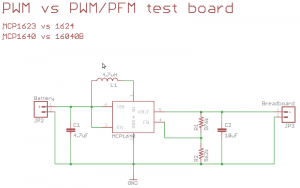
The design is just the reference design from the datasheet.

MCP1623/MCP1624 comparison board schematic

MCP1623/MCP1624 comparison board schematic

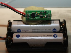
Here it is, finished, attached to a 2xAA battery pack. I quite like how easily it can also plug into a breadboard power supply rails.

MCP1640 eval board, finished, with 2xAAs for size

MCP1640 eval board, finished, with 2xAAs for size

Now, to solder up another one, and actually get the comparisons done!

Costs and parts (mine, you can easily subsitute):

Part (@Mouser)

Cost (singles)
MCP1623/MCP1624

0.429€

0805, 10uF capacitor

0.231€

0805, 4.7uF capacitor

0.19€

0805 1% resistor, 976K

0.035€

0805 1% resistor, 562K

0.066€

4.7uH power inductor, about 1A rated

0.437€

Total cost: 1.38 €. Compared to about 0.65€ or so for using a LDO and two capacitors. Better choices and sourcing for the capacitors and inductor would probably make a big difference.

Note: the MCP1640 family is rated for about 350mA for 3.3V output with 2xAAs, the MCP1623 and 1624 are rated to only 175mA, but that’s more then enough for my needs.

Eagle board/schematic files, as well as gerbers are available in my project space over at github

Pachube dashboard brewery, with pygame and stomp

I send a bunch of data from my sensor network _to_ pachube, but this post is about using pachube as a data _source_ They have this app called a dashboard, which basically gives you some knobs and switches, that are hooked up as live inputs to a pachube data stream.

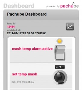
So, that got me thinking, here was a process control GUI pretty much done for me. The permissions are a bit wonky, so I’ll only include a picture here, but basically I get a knob for a set temperature, and a button to turn an alarm on or off. (I can add lots more, but this is all I’ve got set up so far)
Pachube Dashboard control panel

Neat, but now what? Well, the pachube api is pretty easy, so I just hooked up yet another consumer to my local network, (sensor data is dumped into a stomp/activemq message bus here, so that I can have infinite consumers of the data, without ever having to touch the code on my sensor nodes) that pulls data not just from the local network, but also from this pachube dashboard’s feed.

Add a little bit of pygame hackery so I can play sounds, and now I have a heating/cooling warning system for the kettle in the kitchen.

Example output

2011-01-22 11:05:08,649 INFO main - Current temp on probe is 31
2011-01-22 11:05:08,650 DEBUG main - threshold is 74, mode: heating
2011-01-22 11:05:08,650 INFO main - Turning music off.... we're below the threshold
2011-01-22 11:05:13,364 INFO main - Current temp on probe is 32
2011-01-22 11:05:13,365 DEBUG main - threshold is 74, mode: heating
2011-01-22 11:05:13,365 INFO main - Turning music off.... we're below the threshold
2011-01-22 11:07:01,408 INFO main - Current temp on probe is 33
2011-01-22 11:07:01,409 DEBUG main - threshold is 74, mode: heating
2011-01-22 11:07:01,409 INFO main - Turning music off.... we're below the threshold
2011-01-22 11:07:01,409 INFO main - Fetching current dashboard values from pachube, incase they've changed

This is far from any sort of automatic brewery, and was more an experiment in what was possible, and how easily. And it’s still a lot better than having me walk over to the kitchen every 5 minutes to check the current temperature. Now I can just turn the stove on, and get back to serious time wasting on the internet!

Source is over at github, https://github.com/karlp/karlnet/blob/master/consumers/pachube/consumer.pachube.dashboard.py

Things I found:

  • Pachube dashboard only updates if you drag the knobs. Using direct entry doesn’t update the datastream
  • Playing sounds from python is easy, but only when you find the right library, and only when you guess at the documentation a lot. I’ve no idea if this works on windows or osx. I tried a lot of other ways first, all of which failed miserably.