Tag Archives: mrf24j40

Revised MRF24J40 driver code for STM32 and AVR

I meant to post this a while ago, but oh well :) A long time ago I made a basic driver for AVR, then I hacked it up a bit to make it run on the STM32L discovery board. None of the code was common, and the STM32 code was some of my earliest steps in that world. Last summer I started trying to put this all together, but I got busy with other things, and more particularly, I ditched the ST Standard Peripheral Lib and started actively working on libopencm3. Anyway, I eventually got back into project mode, and decided it was time to tidy this all up.

So, here it is. The 3rd edition of my MRF24J40 code. This one should be somewhat more portable to other platforms, as it uses function pointers to set up all the spi and interrupts. (As if anyone else is using this stuff anyway!)

https://github.com/karlp/simrf

There’s still plenty of tidying up that could be done, there always is, but it’s more going to be a base for further work on Contiki, so it’s probably about as good as it’s getting for now.

MRF24J40 driver for STM32

A while ago I put together a C driver for the MRF24J40 802.15.4 modules from microchip. I had been using them as a cheap alternative to xbees in some AVR projects. As I’ve been moving on to STM32 parts for hobby projects, (more power, cheaper) I started off porting my driver code from AVR over to cortex m3.

This has been quite an experience. The arm toolchain experience, and particularly the libc support and general documentation is completely different to, say, avr-libc (AVR-libc is a great project, reallly solid)

However, with lots of learning, and lots of mistakes, I’ve got it all working. It’s a first cut, but the basic features are there. There’s no magic for DMA, and you have to do a lot of the pin setup yourself, but this is Cortex M3, there’s so many pins you could be using for this! I’ve tried to reduce the required function calls as much as possible, but there’s still room for improvement.

    // Required by the user code
    extern void mrf_select(void);  // Chip select, if necessary
    extern void mrf_deselect(void);  // chip deselect, if necessary
    extern uint8_t spi_tx(uint8_t cData);
    extern void _delay_ms(int);  // only used at init time.

This still needs to move to a clear sub project, currently it’s a separate code base to the AVR code.

Get the code now!

More to come, as it gets tidied up and put into use!

Updated MRF24J40 arduino driver

Thanks to pkarck my changes to improve the C library for Microchip’s MRF24J40 802.15.4 modules has been ported to the Arduino library. I’d written an Arduino library some time ago, but hadn’t been maintaining it as I don’t really deal with Arduino much these days. However, it’s gotten some love :) It’s now easier to use, and has support for the power amplifier on the MRF24J40MB modules, if you’re using those. It also makes some quirks I was dealing with in a mixed xbee/mrf24j40 module environment optional. In general, this collects up some of the various reported issues over the last year or so, and I didn’t have to do anything at all!

This is, “teh awesome”.

Downloads:

Fridge Controller – temperature and motor run time, reporting over 802.15.4

One of my most finished projects, mostly because it’s simply much more important than having a battery powered thermometer sitting on a shelf. I brew beer, and serve beer in a converted fridge in my loungeroom. One day, the beer got slow, and what came out was suspicously cold. Turns out the thermostat was broken, so as long as the fridge had power, it was cooling, which resulted in deeply frozen kegs of beer.

It’s a pretty old fridge, that I got free, so I thought about simply getting a new (second hand) fridge and doing the conversion again. A newer fridge would probably be quieter, use less energy, all good things. But, not all fridges are the same shape, and finding one that fit three kegs, and doing all the work of the conversion again just felt like a lot of work. And goddamnit, I’ve been building sensor nodes, I always planned on having nodes that could control things too, so maybe I should just get down to business.

In the end there wasn’t much too it. I’m not doing any fancy PID control, just a set point, and a minimum motor run time, and minimum motor rest time. Initially, it didn’t even listen to any controls from my network, it reported temperature and motor status, but that was it. I had no beer! This was too important to have offline for weeks while I played around 24-480

I got a (massivly overspecced) 25A SSR on ebay, and after a bit of thought about how to keep the cost down, came up with the following schematic:
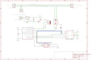
Full schematic for the fridge controller

The clever bit, if I can call it that, was to not even think about making my own power supply for the control logic. Big companies can make 10 gazillion CE marked, compact, safe switch mode power supplies, and consumers can throw them out by the gazillion. I was just going to have a normal euro 2 prong socket, and a surplus phone charger plug pack with the jack cut off and soldered to the board. Presto, cheap _and_ safe. Far far cheaper, faster and easier than I could have done myself. Of course, the extra socket and jacks take up space, but you can only have so much cake.

There’s really not an awful lot more to it than that. I tested this with a teensy board first, because I could use the nice friendly USB port for debugging, then switched to the ATtiny84, and after a bit of fiddling to get USI working for SPI, it all “just worked” I was suitably impressed when the fridge turned on and off at the right times :)

If you want to make this cheaper, you can just drop the 802.15.4 radio altogether. It worked well enough to keep my beer cold but not frozen before I finished the code to listen for new parameters over the air. But, being able to tweak it’s settings is a nice thing.
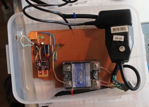
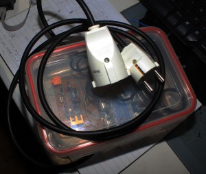
The TMP36, or similar, is wired up on a chopped up length of headphone cable. This is the bit that’s easiest to get wrong. Take care with the pinouts of whatever headphone socket you use, and the way you wire which lead to which part of the 3.5mm stereo plug. (If you get it wrong, you’ll read temperatures like 50, then 80, then 90 degrees Celsius, which will actually be _correct_ if you touch the sensor!)

Things I would have liked to have done:

  • Make the headphone socket mount flush on the wall of the box. Just takes more money and time to get the mounting perfect.
  • Use a panel mount socket for both input and output. It would be much tidier, but it takes yet more space, and yet again, more money

Other notes

The SSR I got really needs 3V+ to control. I was mistakenly feeding it with about 2V, from the wrong side of a resistor divider, early on in testing, and the red LED on the device would light up, so I expected it to properly be switching the live side. However, it seems 2V was enough for the LED, but not enough to actually switch. As soon as I gave it 3V, it behaved perfectly.

There’s no LCD display. Which might have been nice, but really, how often do you look at the temperature of your fridge? Besides, because it’s reporting every 10 seconds to “karlnet” it becomes just another node that the rest of my system stores in databases, graphs, or uploads to pachube

The software has a fairly nice way of working with saved state in EEPROM I learnt recently. I’m quite happy with it :) However, in general, the code is a little bit harder to read, because it contains all the debug for a teensy board, with #defines separating the live code from the test code. This is however a fully fledged real demo of my updated MRF24J40 library code

Downloads

Parts list below.

Part

quantity

price

supplier

25A SSR, 3-25V control, 24-480VAC output

1

7.99 US

ebay

grounded euro socket

1

195 ISK

Byko

grounded euro plug

1

195 ISK

Byko

Ungrounded euro socket

1

181 ISK

Byko

3 strand power cable

2m

363 ISK

Byko

lunch box

1

499 ISK

Húsasmiðjan

Green LED

1

0.05€

Mouser

ATtiny84

1

2.39€

Mouser

MRF24J40MA

1 (optional)

7.46€

Mouser

3.5mm stereo socket, board mount

1

0.44€

Mouser

MCP1702, 3.3V regulator

1

0.39€€

Mouser

TMP36

1

1.58 US

Digikey

1uF capacitors

2

0.40€

Mouser

5V DC plugpack/wallwart

1

500 ISK

Second hand store

2×3 pin header for AVR programming

1

sockets and header pins to comfort

?

?

?

The mouser parts should be available as Shared project 3411228a84 You can substitute something else for the TMP36, that’s just what I had wired up.

Because remember, Digikey are evil, and still refuse to recognise that the 802.15.4 encryption was removed from export restrictions years ago. Digikey, in their infinite wisdom REFUSE TO SHIP 802.15.4 modules to Iceland. We’re terrorists or something.

Updated MRF24J40 library code, now easier to use

I’ve just substantially updated my library code for dealing with Microchip’s MRF24J40 modules on AVR microcontrollers, making it much much easier to use. It’s now based on callbacks for handling rx/tx packets, so you don’t need to know anywhere near as much about the module’s internals anymore. The tradeoff is a bit more ram usage.

mrf_reset and mrf_init now take parameters to ports and pins, so you no longer need to mess around with defines in the library headers any more.

#include "lib_mrf24j.h"
    mrf_reset(&PORTB, PINB5);   // reset pin
    mrf_init(&PORTB, PINB0);  // chip select pin

You no longer need to manually work with the interrupts, you just need to set up the ISR for the pin you’ve chosen to connect to the MRF24J40’s INT pin, for example, for my case, using INT0. (Remember to add a EIMSK |= _BV(INT0); somewhere too!)

ISR(INT0_vect) {
    mrf_interrupt_handler();
}

The interrupt handler takes care of reading in received rf data, and keeping it in a local buffer. It always contains the most recent packet. To do something with the received data, call mrf_check_flags() pretty often. It takes two function pointers as parameters, one which will be called for rx, and one for tx. Here’s a snippet from my main().

    // set the pan id to use
    mrf_pan_write(0xcafe);
    // set our address
    mrf_address16_write(0x6001);
    while (1) {
        // Call this pretty often, at least as often as you expect to be receiving packets
        mrf_check_flags(&handle_rx, &handle_tx);
        if (time_to_send()) {
            mrf_send16(0x4202, 4, "abcd");
        }
    }

And here’s some example rx/tx callback handlers.

void handle_rx(mrf_rx_info_t *rxinfo, uint8_t *rx_buffer) {
    printf_P(PSTR("Received a packet: %d bytes long\n"), rxinfo->frame_length);
    printf_P(PSTR("Packet data:\n"));
    for (int i = 0; i <= rxinfo->frame_length; i++) {
        printf("%x", rx_buffer[i]);
    }
    printf_P(PSTR("\nLQI/RSSI=%d/%d\n"), rxinfo->lqi, rxinfo->rssi);
}
 
void handle_tx(mrf_tx_info_t *txinfo) {
    if (txinfo->tx_ok) {
        printf_P(PSTR("TX went ok, got ack\n"));
    } else {
        printf_P(PSTR("TX failed after %d retries\n"), txinfo->retries);
    }
}

The library code is available here, and also on github (lib_mrf24j)

Complete demo code for a module connected to a PJRC Teensy 2.0 board is here and also on github (You’ll probably have to edit paths in the Makefile)

ttyACM ports missing with teensy arduino on Ubuntu

So, I was reverifying my teensyduino MRF24J40 code recently, and ran into a most infuriating problem, where the /dev/ttyACMXXX devices simply didn’t exist! I could upload code to the teensy via the arduino GUI, and teensy-halfkay could see the device ok, but lsusb didn’t show the device. Weird.

I found lots of stupid terrible advice around the internet, including such insanity as “mknod blah” to simply create the devices, and even such batshit crazy suggestions like updating the rxtx jars that arduino uses. No, no, no.

I still don’t realllly know what’s going on, but someone hinted that because my device might be flooding data out the “serial” (USB CDC ACM serial) port from the instant it’s connected, the linux detection might be getting confused.

Well, I could still program the device ok, somehow, so I tried simply programming the basic teensyduino blink demo. That worked, and it started blinking, and presto, ttyACM0 got created!

NOW I could reprogram with my own mrf24j40 demo code, and I could watch the output on ttyACM0 as expected. Good news.

Except, if I unplug the device, and plug it in again, ttyACM is gone, and doesn’t come back until I reprogram with something else.

Something’s clearly broken, and it happened recently, and I’m grumpy, but at least I have a terrible workaround :(

MRF24J40 with arduino (teensyduino)

Earlier, I’d been working in pure C land, but I know not everyone uses pure C, and sometimes, the arduino environment is a nice easy way to get something prototyped.

So, I turned my mrf24j40 library into an arduino library! It supports all the basic stuff for sending and receiving 802.15.4 frames in a non-beacon network. It’s been tested so far with teensyduino, but it doesn’t use any teensy specific features, so it should work just fine on any arduino style board that has SPI and three spare pins for the reset, interrupt and chip select pins.

You can get the library from github, and like any arduino library, just extract it into your arduino/libraries directory. There are examples for tx only, rx only, and two way data.

Get the MRF24J40 arduino library

The examples are about the extent of the documentation so far, but just email me with questions!

MRF24J40 with AVR SPI (atmega32u4) part3

Update 2011 Oct 6 See Christopher’s comments below! Specifically, line 172 might need to be removed, if you’re using this with a pure mrf24j40 network, or a network that doesn’t contain xbee series 1 devices!
Update 2011 May 29 The sample code and library have been substantially upgraded. See my newer post for the details

And now I have TX working too. The microchip datasheet is _reallly_ sparse on details, and you have to go and get a copy of the actual IEEE 802.15.4 spec (either 2003, or 2006, we’re only concerned with the specification of the MAC header)

I had some problems trying to reconcile bit ordering between the IEEE spec (MSB rightmost, most of the time) and the Microhip docs (MSB leftmost, most of the time) but from there it pretty much just worked. I have yet to try out acknowledgements, I was trying to keep it pretty simple, but working code is working code.

Except… The microchip docs say that you write out one byte with the header length, one byte with the frame length, (header plus packet body) then the header, then the packet body. No gaps anywhere. Try as I might, I had to leave a two byte gap after the header, and before the packet data, when writing to the MRF24J40’s tx normal fifo. (And allow for this in the “length” fields)

I thought I had the addressing modes wrong, and my first two bytes of packet data were being used as some sort of header field I didn’t understand, but I tried out 4 different addressing modes, and in all cases, the data on the received side passed all checksums, and was only consistent with there being a _gap_ in the fifo.

Strange, but workable, as long as you know it’s there. It still makes me feel uncomfortable though.

For reference, I’m using 16 bit (short) addressing for both source and destination, PAN ID header compression (only destination PAN ID is sent) with no security.

The library code is over at github and allows sending packets to existing series one xbee listeners just like this…

mrf_reset();
mrf_init();
// set our PAN ID
mrf_pan_write(0xcafe);
// set our local source address
mrf_address16_write(0x6001);
// send something to a given node
mrf_send16(0x4202, 4, "abcd");

MRF24J40 with AVR SPI (atmega32u4) part2

Update 2011 May 29 The sample code and library have been substantially upgraded. See my newer post for the details.

Good progress last night and today. I get an interrupt for each received packet, working in both promiscuous mode and normal mode.

A fair bit of code to get here, compared to using xbees, but SPI is much much faster, and you don’t need to dick around with baud rates and getting clock timing perfect. UARTs are terrible. From the datasheet, and the little bit of information you can find on the web, it seems that these modules have some rather odd silicon errata. It seems the original datasheet was completely wrong. This is the only thing that I can think of to explain why you need to set up so many registers just to get it to work. The defaults in the silicon are all worthless. Oh well :) It works :)

Note to self: be careful to use mrf_read_long() when you want to use a long address, the address spaces overlap, so using mrf_read_short works, just doesn’t return anything useful.

Working code to get this far, with an AVR host is over at github

MRF24J40 with AVR SPI (atmega32u4) part1

Ouch, this took a lot longer to get started than I thought. SPI is meant to be easy right? All my SPI reads from the MRF24J were returning 0xff.

Turns out that, even with the /SS pin disconnected, if you don’t explicitly set it as an output pin in the DDR register, the AVR falls out of SPI mode if it ever goes low.

So, even though the pin is not connected, (I’m using a general IO pin to do chip select on the radio module) nothing worked until I explicitly made it an output.

And now, presto, I can read data from the MRF24J properly now! Now we can finally move on to the rest of this bring up.

(The MRF24J40 is an 802.15.4 module, with a SPI interface. It’s about 6€, vs about 20€ for xbees, and is on a standard 2.54mm pin spacing, instead of xbee’s 2mm spacing)