Site availability problems…

So, some of you got some breakages today, maybe part of yesterday. Sorry aboutthat :( I’ve moved this blog from some shared hosting onto a VPS from linode.com, along with some other projects from home and other computers. This is the first time I’ve ever actually moved a real live website before, so there was a little bit of learning.

I was clever enough not to try and write any new blog posts while it was transitioning, but what I missed was some apache config that wordpress requires, mod_rewrite. I didn’t have this turned on on my new host at first, and I only checked that the front page came up, not all the links. doh.

So, why the move? Well, it wasn’t because of any problems with the old host. I’ve used ICDSoft.com for ever, (back in 2003) and have been extremely satisfied. Good prices, consistently upgraded plans, and phenomenal support, both the turn around time, and the quality of answers.

However, I have a few other projects lined up, and some of them required/wanted things that just aren’t an option on shared hosting. Spatial databases, python websites via WSGI for performance, that sort of cool things. So I looked at the price of a host that would manage that, and found that, really, I should be able to move all my shared hosting accounts onto one single VPS. false.ekta.is was the first, and in a week or two, if it all goes well, I’ll look at moving some other domains over to it as well.

One of the things I’m already missing however, is managed email. I wanted more flexibility over the web services side, but I was really quite happy having a nice web gui for managing email accounts, and some basic webmail. Now I have to set up postfix/dovecot, and handle mail myself for multiple domains! (And, probably train my mother on a slightly new webmail!)

MRF24J40 with arduino (teensyduino)

Earlier, I’d been working in pure C land, but I know not everyone uses pure C, and sometimes, the arduino environment is a nice easy way to get something prototyped.

So, I turned my mrf24j40 library into an arduino library! It supports all the basic stuff for sending and receiving 802.15.4 frames in a non-beacon network. It’s been tested so far with teensyduino, but it doesn’t use any teensy specific features, so it should work just fine on any arduino style board that has SPI and three spare pins for the reset, interrupt and chip select pins.

You can get the library from github, and like any arduino library, just extract it into your arduino/libraries directory. There are examples for tx only, rx only, and two way data.

Get the MRF24J40 arduino library

The examples are about the extent of the documentation so far, but just email me with questions!

MRF24J40 with AVR SPI (atmega32u4) part3

Update 2011 Oct 6 See Christopher’s comments below! Specifically, line 172 might need to be removed, if you’re using this with a pure mrf24j40 network, or a network that doesn’t contain xbee series 1 devices!
Update 2011 May 29 The sample code and library have been substantially upgraded. See my newer post for the details

And now I have TX working too. The microchip datasheet is _reallly_ sparse on details, and you have to go and get a copy of the actual IEEE 802.15.4 spec (either 2003, or 2006, we’re only concerned with the specification of the MAC header)

I had some problems trying to reconcile bit ordering between the IEEE spec (MSB rightmost, most of the time) and the Microhip docs (MSB leftmost, most of the time) but from there it pretty much just worked. I have yet to try out acknowledgements, I was trying to keep it pretty simple, but working code is working code.

Except… The microchip docs say that you write out one byte with the header length, one byte with the frame length, (header plus packet body) then the header, then the packet body. No gaps anywhere. Try as I might, I had to leave a two byte gap after the header, and before the packet data, when writing to the MRF24J40’s tx normal fifo. (And allow for this in the “length” fields)

I thought I had the addressing modes wrong, and my first two bytes of packet data were being used as some sort of header field I didn’t understand, but I tried out 4 different addressing modes, and in all cases, the data on the received side passed all checksums, and was only consistent with there being a _gap_ in the fifo.

Strange, but workable, as long as you know it’s there. It still makes me feel uncomfortable though.

For reference, I’m using 16 bit (short) addressing for both source and destination, PAN ID header compression (only destination PAN ID is sent) with no security.

The library code is over at github and allows sending packets to existing series one xbee listeners just like this…

mrf_reset();
mrf_init();
// set our PAN ID
mrf_pan_write(0xcafe);
// set our local source address
mrf_address16_write(0x6001);
// send something to a given node
mrf_send16(0x4202, 4, "abcd");

MRF24J40 with AVR SPI (atmega32u4) part2

Update 2011 May 29 The sample code and library have been substantially upgraded. See my newer post for the details.

Good progress last night and today. I get an interrupt for each received packet, working in both promiscuous mode and normal mode.

A fair bit of code to get here, compared to using xbees, but SPI is much much faster, and you don’t need to dick around with baud rates and getting clock timing perfect. UARTs are terrible. From the datasheet, and the little bit of information you can find on the web, it seems that these modules have some rather odd silicon errata. It seems the original datasheet was completely wrong. This is the only thing that I can think of to explain why you need to set up so many registers just to get it to work. The defaults in the silicon are all worthless. Oh well :) It works :)

Note to self: be careful to use mrf_read_long() when you want to use a long address, the address spaces overlap, so using mrf_read_short works, just doesn’t return anything useful.

Working code to get this far, with an AVR host is over at github

MRF24J40 with AVR SPI (atmega32u4) part1

Ouch, this took a lot longer to get started than I thought. SPI is meant to be easy right? All my SPI reads from the MRF24J were returning 0xff.

Turns out that, even with the /SS pin disconnected, if you don’t explicitly set it as an output pin in the DDR register, the AVR falls out of SPI mode if it ever goes low.

So, even though the pin is not connected, (I’m using a general IO pin to do chip select on the radio module) nothing worked until I explicitly made it an output.

And now, presto, I can read data from the MRF24J properly now! Now we can finally move on to the rest of this bring up.

(The MRF24J40 is an 802.15.4 module, with a SPI interface. It’s about 6€, vs about 20€ for xbees, and is on a standard 2.54mm pin spacing, instead of xbee’s 2mm spacing)

Vodafone 845 review. (Huawei 8120/Huawei Joy)

I needed a new phone, my old sony ericsson G502 had been misbehaving for months, (rebooting whenever it received a phone call or an SMS) I had been hoping to hold off on a new phone for another six months or so, to let the newer android phones trickle down a bit in price. I’m not really big on buying super expensive phones. I’d been burnt before, buying a “high end” phone that was good on paper, but had a terribly clunky interface, poorly integrated, or just unreliable physically.

So, the phone. It’s nice and cheap, runs android 2.1. I paid a touch over 20k ISK (about 120 €) which makes it a nice midrange phone, the sort I’ve become happy with. (After also being burnt by super low end phones that also had software problems) You can read the boring paper specs elsewhere. It works I guess. The GPS works very well, great reception, but it will suck your battery dry in a couple of hours. (At least, using Maverick (light) to actually record a track and so on)

It has a resistive touchscreen. This is actually fine. It’s not the super light feather touch of an iphone, but it works just fine. It does take a bit of getting used to, after having a standard regular button phone for years and years. The predictive text is excellent, doing a good job of learning. The autocorrect is also excellent. You can have three keyboards, one qwerty style, with one letter per button, one phone style, with three letters per button, and what I’m told is blackberry style, with two letters per button. I prefer the qwerty style, but sometimes the fat fingers hit a neighbouring button, and the autocorrect does a really great job of working around it.

I have not yet found out how to enter icelandic letters, which means that it’s surely possible, but it wasn’t thought out well enough, especially not for a phone sold in Iceland.

The barcode scanner, or probably more correctly, the camera on the phone, isn’t capable of dealing with regular “2D” barcodes, it can’t focus well enough up close, though it does ok with medium and larger QR codes. (Again, small QR codes are just too small for it)

The camera white balance is pretty good, arguably better than my canon, but canon is notorious for auto white balance being warm yellow under incandescent lights anyway. The shutton button is a soft button, so I sometimes find it hard to keep the camera still enough while taking a picture. I don’t really use the camera much though, as I carry a “proper” camera with me all the time anyway.

The microSD slot is only accessible by taking the back off the phone. And android, for god knows what reason, at least in version 2.1, makes it more difficult than it should to access the card over wifi.

The wifi works just fine, no problems there. Again, it eats battery. With wifi turned on, you’ll get a day, tops. With wifi off, or only on when it’s being used, you can easily get a few days.

It has recently (it’s nearly two months old) decided to “snooze” forever. I liked the fact that I could change the snooze time for the alarm clock, but recently, I press snooze, and instead of being woken again in 5 minutes, I wake up two hours later, the phone says the alarm is “snoozing” but it hasn’t rung again. This is a rather serious failure.

The phone sometimes, (4 times or more, far far too often) decides that it simply can’t see any network service. (This is not like americans complaining about AT&T’s GSM network, this is downtown Reykjavik, where phones just work. I’ve never had a phone complain about no service in town) The phone just sits there with an X on the service bars, saying no service. Every 5-10 minutes, it power cycles the radio? and I get that awesome buzzing in the speakers (like when you’re just about to get an SMS?) and it will see network service for a minute or two before dying again. This _sucks_ battery. I was late to work one day when the phone ran out of battery over night. I’ve only been able to fix this by taking the sim card out and putting it back in again.

The phone has a “drag to unlock” screen, but seems to unlock itself in my pocket, and do really helpful things like make phone calls to recently called people. Why it always makes phone calls, instead of starting some other app, or the camera, or anything else, I don’t know. This is also annoying.

Is it a terrible phone? hmm, hard to say, the random calling people is pretty crap, but at least the other ones I can (somewhat) control. On my old Sony Ericsson G502, I simply had no control. The phone might or might not reboot if I tried to use it. On my older Nokia 1200, I could send SMSs, but they might not actually get sent. (Known issue with that phone, pity, it’s an otherwise _excellent_ phone, superb battery life, simple, compact, rugged, includes a torch, and super cheap) The alarm clock issue is new, and also rather annoying. Being able to comfortably use web things on the phone is nice though. It was also (relatively) cheap, so I don’t feel particularly burnt. (The same money would get me yet another generic sony ericsson, or nokia, with no particular features whatsoever, and both those companies have been going downhill software and reliability wise)

I could go on and on and on and on, talking about things I like and don’t like, but really, who’s going to read all this anyway?

Summary: It’s got problems, which might become total failure problems, but none of them are to do with the resistive touchscreen or the slower processor, which is all you will hear about in any other reviews of this phone.
Valentines day heart chaser

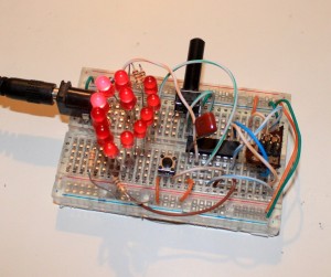
I’ll be doing something a bit more romantic for Konudagur, next week, but seeing as my girlfriend was working late on Valentines day, I took a break from wireless and frequency counters and software, and whipped up a little love heart.

Valentines LED Heart chaser

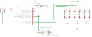
Not much to it really, just a bunch of LEDs arranged in a heart, driven straight off general IO pins of an ATtiny84, with a pot to adjust the delay between parts. The heart is 12 LEDs, in three groups of four, and can do a nice slow chase, flicker, or appear solid on.

In reality, my board has some extra current limiting resistors, as I didn’t have 12 exactly the same LEDs, and the different diode drops between the different LEDs I had meant they couldn’t share the same resistors. In reality, I also tried to hook up a pushbutton and toggle between two patterns of lights, but I have forgotten everything I learned about switch debouncing, and ran out of time.

Code is available at github, considered to be public domain.

The schematic is available at github as well, in eagle format.
Valentines chaser schematic

And, here’s a video of it, you can see the different LEDs have a slightly different colour & intensity. (And that I turned the pot the wrong way at first :)

3.3v from 2xAAs, switching regulators, learning surface mount

I’ve been running a couple of sensor nodes here on hacked together breadboards, with old camera batteries, telephone cable and string, but recently decided it was time to make some of these designs a little bit more permanent. So it was into CAD land, making the first PCBs I’ve had made since I left university. But one thing that I’ve been wanting, is a better power supply. Yes, 3.3V low dropout regulators, like the MCP1702, are cheap and easy and reliable. But, you really need at least 3xAAs. And in my mind, 3xAAs is just awkward. 4xAAs is less awkward, but you’re starting to talk about serious heft there, and besides, with a bit of care, 2xAAs should last a year or so, so 4 is just ridiculous.

But, I still wanted it to be cheap. Switching regulators have been around for ages, in various shapes and sizes, but they normally involve inductors and/or schottkey diodes, or both, and a fistful of caps. Oh, and these days, they’re almost invariably surface mount. I was looking at various parts used by other people, and their cost, size, required components, and so on, and found the MCP1640 family. One of the things that is really important for a battery powered sensor node is the idle current, and these both have that, and interestingly, also have an option of switching into PFM mode when load current is very low, so they draw even less power.

One traditional issue with switching regulators is the noise on the power supply lines, and when you want to use that as an ADC source, this can really be an issue. And on the datasheets, when it switches into PFM mode at low load current, the ripple is really quite noticeable. But, would my “active” load be above or below the threshold? I wasn’t sure, and wasn’t prepared to trust my estimates, and well, the part was available both with and without the PFM at low load feature.

So I got a couple of each, and laid out a tiny little sample board. Then I could try it out both supplies, and just damn well test it :)

So far, I’ve only soldered up one of them, and it’s working fine. This was far and away the smallest soldering I’ve done before. I went for 0805 passives, and the regulator comes in SOT23-6. A bit of a learning experience, I found this article at infidigm.net to be very useful. Don’t laugh too much at the horribly wonky parts :)

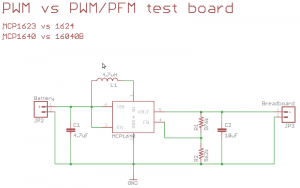
The design is just the reference design from the datasheet.

MCP1623/MCP1624 comparison board schematic

MCP1623/MCP1624 comparison board schematic

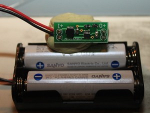
Here it is, finished, attached to a 2xAA battery pack. I quite like how easily it can also plug into a breadboard power supply rails.

MCP1640 eval board, finished, with 2xAAs for size

MCP1640 eval board, finished, with 2xAAs for size

Now, to solder up another one, and actually get the comparisons done!

Costs and parts (mine, you can easily subsitute):

Part (@Mouser)

Cost (singles)
MCP1623/MCP1624

0.429€

0805, 10uF capacitor

0.231€

0805, 4.7uF capacitor

0.19€

0805 1% resistor, 976K

0.035€

0805 1% resistor, 562K

0.066€

4.7uH power inductor, about 1A rated

0.437€

Total cost: 1.38 €. Compared to about 0.65€ or so for using a LDO and two capacitors. Better choices and sourcing for the capacitors and inductor would probably make a big difference.

Note: the MCP1640 family is rated for about 350mA for 3.3V output with 2xAAs, the MCP1623 and 1624 are rated to only 175mA, but that’s more then enough for my needs.

Eagle board/schematic files, as well as gerbers are available in my project space over at github

Pachube dashboard brewery, with pygame and stomp

I send a bunch of data from my sensor network _to_ pachube, but this post is about using pachube as a data _source_ They have this app called a dashboard, which basically gives you some knobs and switches, that are hooked up as live inputs to a pachube data stream.

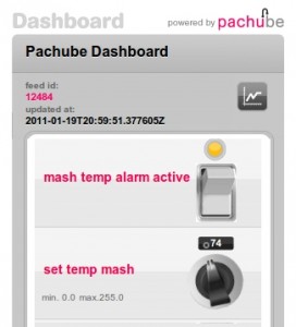
So, that got me thinking, here was a process control GUI pretty much done for me. The permissions are a bit wonky, so I’ll only include a picture here, but basically I get a knob for a set temperature, and a button to turn an alarm on or off. (I can add lots more, but this is all I’ve got set up so far)
Pachube Dashboard control panel

Neat, but now what? Well, the pachube api is pretty easy, so I just hooked up yet another consumer to my local network, (sensor data is dumped into a stomp/activemq message bus here, so that I can have infinite consumers of the data, without ever having to touch the code on my sensor nodes) that pulls data not just from the local network, but also from this pachube dashboard’s feed.

Add a little bit of pygame hackery so I can play sounds, and now I have a heating/cooling warning system for the kettle in the kitchen.

Example output

2011-01-22 11:05:08,649 INFO main - Current temp on probe is 31
2011-01-22 11:05:08,650 DEBUG main - threshold is 74, mode: heating
2011-01-22 11:05:08,650 INFO main - Turning music off.... we're below the threshold
2011-01-22 11:05:13,364 INFO main - Current temp on probe is 32
2011-01-22 11:05:13,365 DEBUG main - threshold is 74, mode: heating
2011-01-22 11:05:13,365 INFO main - Turning music off.... we're below the threshold
2011-01-22 11:07:01,408 INFO main - Current temp on probe is 33
2011-01-22 11:07:01,409 DEBUG main - threshold is 74, mode: heating
2011-01-22 11:07:01,409 INFO main - Turning music off.... we're below the threshold
2011-01-22 11:07:01,409 INFO main - Fetching current dashboard values from pachube, incase they've changed

This is far from any sort of automatic brewery, and was more an experiment in what was possible, and how easily. And it’s still a lot better than having me walk over to the kitchen every 5 minutes to check the current temperature. Now I can just turn the stove on, and get back to serious time wasting on the internet!

Source is over at github, https://github.com/karlp/karlnet/blob/master/consumers/pachube/consumer.pachube.dashboard.py

Things I found:

  • Pachube dashboard only updates if you drag the knobs. Using direct entry doesn’t update the datastream
  • Playing sounds from python is easy, but only when you find the right library, and only when you guess at the documentation a lot. I’ve no idea if this works on windows or osx. I tried a lot of other ways first, all of which failed miserably.

AVR ICSP on a breadboard

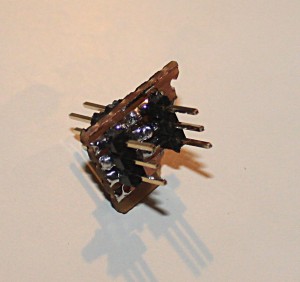
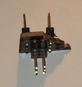
Update 2011-02-20: I made a new one for some another board, so I took a couple more pictures..

I thought I’d drawn this up a while ago, but seems I never actually got around to it. Because I prefer a proper programming editor (ie, NOT the arduino environment) I normally end up using plain old C and plain old ICSP programmers like the USBTinyISP

Anyway, the 2×3, 6 pin programming header doesn’t really plug into a breadboard, so I took some strip board, put a 2×3 on the top, and two 1x3s on the bottom spread out enough to cross the gap on the breadboard.

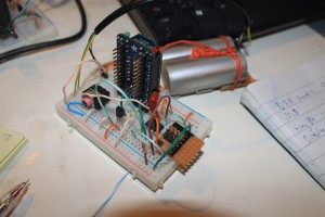
Then, just wire up the header to the MOSI/MISO/SCK/Reset pins on whatever device you’re using.Breadboard ICSP programmer in-situ in a wireless sensor node
AVR ICSP programming header view 2
AVR ICSP breadboard programming header