Category Archives: karlnet

Fridge Controller – temperature and motor run time, reporting over 802.15.4

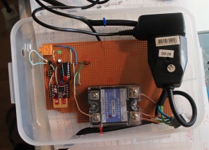
One of my most finished projects, mostly because it’s simply much more important than having a battery powered thermometer sitting on a shelf. I brew beer, and serve beer in a converted fridge in my loungeroom. One day, the beer got slow, and what came out was suspicously cold. Turns out the thermostat was broken, so as long as the fridge had power, it was cooling, which resulted in deeply frozen kegs of beer.

It’s a pretty old fridge, that I got free, so I thought about simply getting a new (second hand) fridge and doing the conversion again. A newer fridge would probably be quieter, use less energy, all good things. But, not all fridges are the same shape, and finding one that fit three kegs, and doing all the work of the conversion again just felt like a lot of work. And goddamnit, I’ve been building sensor nodes, I always planned on having nodes that could control things too, so maybe I should just get down to business.

In the end there wasn’t much too it. I’m not doing any fancy PID control, just a set point, and a minimum motor run time, and minimum motor rest time. Initially, it didn’t even listen to any controls from my network, it reported temperature and motor status, but that was it. I had no beer! This was too important to have offline for weeks while I played around 24-480

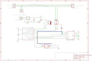
I got a (massivly overspecced) 25A SSR on ebay, and after a bit of thought about how to keep the cost down, came up with the following schematic:

Full schematic for the fridge controller

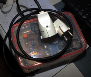
The clever bit, if I can call it that, was to not even think about making my own power supply for the control logic. Big companies can make 10 gazillion CE marked, compact, safe switch mode power supplies, and consumers can throw them out by the gazillion. I was just going to have a normal euro 2 prong socket, and a surplus phone charger plug pack with the jack cut off and soldered to the board. Presto, cheap _and_ safe. Far far cheaper, faster and easier than I could have done myself. Of course, the extra socket and jacks take up space, but you can only have so much cake.

There’s really not an awful lot more to it than that. I tested this with a teensy board first, because I could use the nice friendly USB port for debugging, then switched to the ATtiny84, and after a bit of fiddling to get USI working for SPI, it all “just worked” I was suitably impressed when the fridge turned on and off at the right times :)

If you want to make this cheaper, you can just drop the 802.15.4 radio altogether. It worked well enough to keep my beer cold but not frozen before I finished the code to listen for new parameters over the air. But, being able to tweak it’s settings is a nice thing.

The TMP36, or similar, is wired up on a chopped up length of headphone cable. This is the bit that’s easiest to get wrong. Take care with the pinouts of whatever headphone socket you use, and the way you wire which lead to which part of the 3.5mm stereo plug. (If you get it wrong, you’ll read temperatures like 50, then 80, then 90 degrees Celsius, which will actually be _correct_ if you touch the sensor!)

Things I would have liked to have done:

  • Make the headphone socket mount flush on the wall of the box. Just takes more money and time to get the mounting perfect.
  • Use a panel mount socket for both input and output. It would be much tidier, but it takes yet more space, and yet again, more money

Other notes

The SSR I got really needs 3V+ to control. I was mistakenly feeding it with about 2V, from the wrong side of a resistor divider, early on in testing, and the red LED on the device would light up, so I expected it to properly be switching the live side. However, it seems 2V was enough for the LED, but not enough to actually switch. As soon as I gave it 3V, it behaved perfectly.

There’s no LCD display. Which might have been nice, but really, how often do you look at the temperature of your fridge? Besides, because it’s reporting every 10 seconds to “karlnet” it becomes just another node that the rest of my system stores in databases, graphs, or uploads to pachube

The software has a fairly nice way of working with saved state in EEPROM I learnt recently. I’m quite happy with it :) However, in general, the code is a little bit harder to read, because it contains all the debug for a teensy board, with #defines separating the live code from the test code. This is however a fully fledged real demo of my updated MRF24J40 library code

Downloads

Parts list below.

Part

quantity

price

supplier

25A SSR, 3-25V control, 24-480VAC output

1

7.99 US

ebay

grounded euro socket

1

195 ISK

Byko

grounded euro plug

1

195 ISK

Byko

Ungrounded euro socket

1

181 ISK

Byko

3 strand power cable

2m

363 ISK

Byko

lunch box

1

499 ISK

Húsasmiðjan

Green LED

1

0.05€

Mouser

ATtiny84

1

2.39€

Mouser

MRF24J40MA

1 (optional)

7.46€

Mouser

3.5mm stereo socket, board mount

1

0.44€

Mouser

MCP1702, 3.3V regulator

1

0.39€€

Mouser

TMP36

1

1.58 US

Digikey

1uF capacitors

2

0.40€

Mouser

5V DC plugpack/wallwart

1

500 ISK

Second hand store

2×3 pin header for AVR programming

1

sockets and header pins to comfort

?

?

?

The mouser parts should be available as Shared project 3411228a84 You can substitute something else for the TMP36, that’s just what I had wired up.

Because remember, Digikey are evil, and still refuse to recognise that the 802.15.4 encryption was removed from export restrictions years ago. Digikey, in their infinite wisdom REFUSE TO SHIP 802.15.4 modules to Iceland. We’re terrorists or something.
Dresden Elektronik ATmega128RFA1 breakout boards, deRFmega128

I’ll write up more about the parts themselves later, but I finally got boards made for Dresden Elektronik’s deRFmega128 modules, both made, and now assembled and tested. Briefly, these are a module with Atmel’s ATmega128RFA1 (a combined ATmega128 with a 802.15.4 2.4 Ghz transceiver on a single chip) with either a chip antenna, or a connector for your own antenna. These are TINY, and they also manage to pack a 1Mbit EEPROM on the module, for your own use. All for 21€

I’ve only tested a basic blinky thing so far, but it’s good to know that I can finally start doing something with these cool modules.

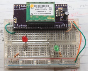
Here’s one up on a breadboard.

These modules are the same length as PJRC’s Teensy boards, but they have leads on 1.27mm pitch, not 2.54mm pitch. Lots more pins, but you’ll need some parts. For the 1.27mm socket holders, I ordered direct from Samtec. [1] Dresden recommends SLM Series, but I ordered SMS series. It may have been price, or availability, who knows. I ordered SMS-123-02-G-S, and the pins are really way too long on those. SMS-01-G-S would have been a better choice. Also, and I don’t know if the SLM would have been better, but I have a little bit of a hard time getting the modules into these sockets. They seem to “spring” out a little bit, to point that I initially thought I had failed to make my pcbs properly. Some of the pins weren’t making good contact. I have my modules mounted “upside down” with the silver RF can facing down. That’s the way the module leads are longest, and gold, and the only way they fit, when I was testing out the sockets and the modules. (Before the boards got here)

I’ve now found, that they will fit in nicely with the metal can UP and click into place nicely, but that’s not pin compatible with the AVR ISP header, or the power supply I put on the breakout.

So, I have some breakouts that work just fine, if you solder the part in, and probably well enough for development before your own boards, but I’m probably going to respin them :( The modules are cool, and they just came out with a pin compatible module, with an ARM7 core, instead of the ATmega128.

I still have a spare board from this revision though, if you are at all interested, I can send you one :)

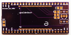
Here’s the board itself

Note, it already says rev3. That’s a story for another day :)

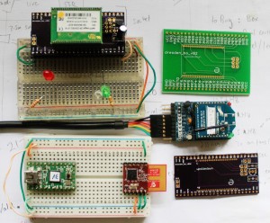
And to leave you, a picture of the different RF modules I’ve been working with here recently.

deRFmega128, Teensy v2 + MRF24J40MA, Xbee Series 1 + adafruit board

The current board files are available from https://github.com/karlp/karlnet/tree/master/experiments/dresden

The very basic blinking demo is also at github, should you really want it :)

[1] You can pretty much forget about getting 23pin headers from either digikey or mouser. Samtec were prompt, and had cheap enough shipping, relatively speaking. (I ordered a dozen)

MRF24J40 with AVR SPI (atmega32u4) part3

Update 2011 Oct 6 See Christopher’s comments below! Specifically, line 172 might need to be removed, if you’re using this with a pure mrf24j40 network, or a network that doesn’t contain xbee series 1 devices!
Update 2011 May 29 The sample code and library have been substantially upgraded. See my newer post for the details

And now I have TX working too. The microchip datasheet is _reallly_ sparse on details, and you have to go and get a copy of the actual IEEE 802.15.4 spec (either 2003, or 2006, we’re only concerned with the specification of the MAC header)

I had some problems trying to reconcile bit ordering between the IEEE spec (MSB rightmost, most of the time) and the Microhip docs (MSB leftmost, most of the time) but from there it pretty much just worked. I have yet to try out acknowledgements, I was trying to keep it pretty simple, but working code is working code.

Except… The microchip docs say that you write out one byte with the header length, one byte with the frame length, (header plus packet body) then the header, then the packet body. No gaps anywhere. Try as I might, I had to leave a two byte gap after the header, and before the packet data, when writing to the MRF24J40’s tx normal fifo. (And allow for this in the “length” fields)

I thought I had the addressing modes wrong, and my first two bytes of packet data were being used as some sort of header field I didn’t understand, but I tried out 4 different addressing modes, and in all cases, the data on the received side passed all checksums, and was only consistent with there being a _gap_ in the fifo.

Strange, but workable, as long as you know it’s there. It still makes me feel uncomfortable though.

For reference, I’m using 16 bit (short) addressing for both source and destination, PAN ID header compression (only destination PAN ID is sent) with no security.

The library code is over at github and allows sending packets to existing series one xbee listeners just like this…

mrf_reset();
mrf_init();
// set our PAN ID
mrf_pan_write(0xcafe);
// set our local source address
mrf_address16_write(0x6001);
// send something to a given node
mrf_send16(0x4202, 4, "abcd");

3.3v from 2xAAs, switching regulators, learning surface mount

I’ve been running a couple of sensor nodes here on hacked together breadboards, with old camera batteries, telephone cable and string, but recently decided it was time to make some of these designs a little bit more permanent. So it was into CAD land, making the first PCBs I’ve had made since I left university. But one thing that I’ve been wanting, is a better power supply. Yes, 3.3V low dropout regulators, like the MCP1702, are cheap and easy and reliable. But, you really need at least 3xAAs. And in my mind, 3xAAs is just awkward. 4xAAs is less awkward, but you’re starting to talk about serious heft there, and besides, with a bit of care, 2xAAs should last a year or so, so 4 is just ridiculous.

But, I still wanted it to be cheap. Switching regulators have been around for ages, in various shapes and sizes, but they normally involve inductors and/or schottkey diodes, or both, and a fistful of caps. Oh, and these days, they’re almost invariably surface mount. I was looking at various parts used by other people, and their cost, size, required components, and so on, and found the MCP1640 family. One of the things that is really important for a battery powered sensor node is the idle current, and these both have that, and interestingly, also have an option of switching into PFM mode when load current is very low, so they draw even less power.

One traditional issue with switching regulators is the noise on the power supply lines, and when you want to use that as an ADC source, this can really be an issue. And on the datasheets, when it switches into PFM mode at low load current, the ripple is really quite noticeable. But, would my “active” load be above or below the threshold? I wasn’t sure, and wasn’t prepared to trust my estimates, and well, the part was available both with and without the PFM at low load feature.

So I got a couple of each, and laid out a tiny little sample board. Then I could try it out both supplies, and just damn well test it :)

So far, I’ve only soldered up one of them, and it’s working fine. This was far and away the smallest soldering I’ve done before. I went for 0805 passives, and the regulator comes in SOT23-6. A bit of a learning experience, I found this article at infidigm.net to be very useful. Don’t laugh too much at the horribly wonky parts :)

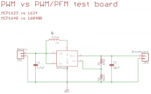
The design is just the reference design from the datasheet.

MCP1623/MCP1624 comparison board schematic

MCP1623/MCP1624 comparison board schematic

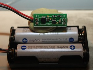
Here it is, finished, attached to a 2xAA battery pack. I quite like how easily it can also plug into a breadboard power supply rails.

MCP1640 eval board, finished, with 2xAAs for size

MCP1640 eval board, finished, with 2xAAs for size

Now, to solder up another one, and actually get the comparisons done!

Costs and parts (mine, you can easily subsitute):

Part (@Mouser)

Cost (singles)
MCP1623/MCP1624

0.429€

0805, 10uF capacitor

0.231€

0805, 4.7uF capacitor

0.19€

0805 1% resistor, 976K

0.035€

0805 1% resistor, 562K

0.066€

4.7uH power inductor, about 1A rated

0.437€

Total cost: 1.38 €. Compared to about 0.65€ or so for using a LDO and two capacitors. Better choices and sourcing for the capacitors and inductor would probably make a big difference.

Note: the MCP1640 family is rated for about 350mA for 3.3V output with 2xAAs, the MCP1623 and 1624 are rated to only 175mA, but that’s more then enough for my needs.

Eagle board/schematic files, as well as gerbers are available in my project space over at github

Pachube dashboard brewery, with pygame and stomp

I send a bunch of data from my sensor network _to_ pachube, but this post is about using pachube as a data _source_ They have this app called a dashboard, which basically gives you some knobs and switches, that are hooked up as live inputs to a pachube data stream.

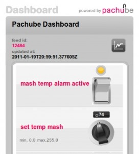
So, that got me thinking, here was a process control GUI pretty much done for me. The permissions are a bit wonky, so I’ll only include a picture here, but basically I get a knob for a set temperature, and a button to turn an alarm on or off. (I can add lots more, but this is all I’ve got set up so far)
Pachube Dashboard control panel

Neat, but now what? Well, the pachube api is pretty easy, so I just hooked up yet another consumer to my local network, (sensor data is dumped into a stomp/activemq message bus here, so that I can have infinite consumers of the data, without ever having to touch the code on my sensor nodes) that pulls data not just from the local network, but also from this pachube dashboard’s feed.

Add a little bit of pygame hackery so I can play sounds, and now I have a heating/cooling warning system for the kettle in the kitchen.

Example output

2011-01-22 11:05:08,649 INFO main - Current temp on probe is 31
2011-01-22 11:05:08,650 DEBUG main - threshold is 74, mode: heating
2011-01-22 11:05:08,650 INFO main - Turning music off.... we're below the threshold
2011-01-22 11:05:13,364 INFO main - Current temp on probe is 32
2011-01-22 11:05:13,365 DEBUG main - threshold is 74, mode: heating
2011-01-22 11:05:13,365 INFO main - Turning music off.... we're below the threshold
2011-01-22 11:07:01,408 INFO main - Current temp on probe is 33
2011-01-22 11:07:01,409 DEBUG main - threshold is 74, mode: heating
2011-01-22 11:07:01,409 INFO main - Turning music off.... we're below the threshold
2011-01-22 11:07:01,409 INFO main - Fetching current dashboard values from pachube, incase they've changed

This is far from any sort of automatic brewery, and was more an experiment in what was possible, and how easily. And it’s still a lot better than having me walk over to the kitchen every 5 minutes to check the current temperature. Now I can just turn the stove on, and get back to serious time wasting on the internet!

Source is over at github, https://github.com/karlp/karlnet/blob/master/consumers/pachube/consumer.pachube.dashboard.py

Things I found:

  • Pachube dashboard only updates if you drag the knobs. Using direct entry doesn’t update the datastream
  • Playing sounds from python is easy, but only when you find the right library, and only when you guess at the documentation a lot. I’ve no idea if this works on windows or osx. I tried a lot of other ways first, all of which failed miserably.

Database size, column types, and retention policies

So, earlier I mentioned that I had a 700meg database of samples, and wasn’t even looking at them.

I started trying to look at them, and quickly had to add some indexes, ballooning the db out to about 950meg. This was clearly going in the wrong direction.

I looked at the table schema, and quickly realised that keeping the sensor sample time (a unix timestamp) as a string instead of a number was pretty wasteful, and likewise for the sensor type and node id. Although both of those can be given meaningful names, all firmware on the nodes have those as numbers as well, because it has to go over the wire(less)

So, simply changing the database schema from some string columns to some integer columns, and my calculator tells me I’ve gone from 90 bytes per sample, down to 32 bytes per sample.

Much better. And now that the date sample is a proper number, searching the db for date windows is much faster, without even needing the index.

And for added deliciousness, the python consumer, that writes into this database didn’t have to change at all, is it a string, is it an integer? It’s both!

That’s all well and good, but it’s still going to just keep on growing forever and ever, and with samples every 5 seconds, and (currently) 3 nodes with 2-3 sensors on each one, this isn’t going to slow down.

Do I really really care about that resolution of data much longer than a few days/weeks/month in the past? Shouldn’t I really just be averaging the older data out to get some general trends? Perhaps :) And that’s exactly what RRDtool is for, I just find it a little obtuse to use at times. (Mostly, I have to decide, permanently and forever, right now, exactly how long I do want to keep things. I didn’t want to have to decide that)

Footnote: For the curious, the schemas for sqlite3 were

CREATE TABLE karlnet_sensor (sampleTime text, node text, sensorType text, sensorRaw real, sensorValue real);
CREATE TABLE karlnet_sensor2 (sampleTime integer, node integer, sensorType integer, sensorRaw real, sensorValue real);

And 32bytes per sample, with 4.7 million samples for the last three months, is still 150meg (I tossed some old data, when the node firmware was all in flux anyway)

Back in action… power meters and sensor probes.

So, after a six month break or so, and a 700meg database of sensor data I wasn’t actually looking at, I’m back in action!

I finally bit the bullet, bought a commercial power meter, and finished off my power meter project. It’s based on: Open Energy Monitor v3 but mine is in regular C, instead of arduinoC, because that fits in better with the common code for the rest of my nodes. (Not all my nodes are arduino compatible hardware) Calibrating was a bit of a pain, but it’s working! Now to get it boxed up and attached somewhere a bit more useful. It’s currently tying up my only spare AVR chip, so it’s not live.

What else? I bought some sexy radio boards from Dresden Elektronik that look pretty neat. Basically combining an AVR with an xbee, in a smaller package, for the same price. Why did I ever actually get into xbees? I should have done more research on the available radio options :) If I wanted just radios, I should have looked at these MRF24740 radios from Microchip I’ve got some on their way, but haven’t tried them out yet.

One problem with both the xbees and the dresden boards is that they’re on 2mm and 1.27mm pitch pin headers. This is nice and compact, but not very friendly for breadboards :)

Which brings me to customer service! Dresden actually phoned me up about 2 weeks after I bought the boards to check how I was going, and if there was any engineering help they could give me! Awesome! Pity Icelandic customs had only finally released the modules to me the day before, and I’d only just realised just how fine pitch 1.27mm really was :) Again, I should have read a bit more first.

Still on customer service, I ordered some pin headers from Samtec Seems 23pin female sockets, 1.27mm pitch are not something that mouser/farnell/RS stock, but Samtec is actually one of those lovely manufacturers who ship small quantities direct, worldwide, for reasonable prices! Excellent! So excellent in fact, that they shipped out the 1.27mm sockets as soon as they were ready, and the 2mm ones (for more xbee based boards) two days later. So I get two _enormous_ toblerone packages (triangle tube, about 13-14cm/side, 90-100cm long?) Delivered separately, with 20 rather teensy tiny little sockets all up. I’m sure if I was in a hurry this would have been excellent, but it felt a little excessive really :)

But socket headers are not going to help on a breadboard, it’s still fine pitch. So I’m also back into PCB design again, something I haven’t done since uni.

Lots of excitement. Oh yeah, and software too of course. I mentioned at the start that I wasn’t really looking at any of the data. Well, now, I am and also in other ways making more use of the fact that I was uploading all this data to pachube for so long!

It’s good to be back, but it has meant I’ve been spending far too much time in front of the computer again :)

Pachube exporting now in place

Pachube is an interesting looking site. They don’t really seem to have all that many users, but hey, if they’re going to graph all my data for me, cool. It’s not exactly top secret information. I still don’t have things like the (new!) humidity sensor calibrated, but hey, it’s uploading, and it’s graphing.
TinyTemp has the initial atTiny85 based temperature sensor, and FreqyTemp has the new mega328 based temperature and relative humidity sensor. (more on that still to come)

The max/min values are off from some errors I was getting while I was setting this up, but hey, the more data exports the better right?
Github has the code