I’ve been running a couple of sensor nodes here on hacked together breadboards, with old camera batteries, telephone cable and string, but recently decided it was time to make some of these designs a little bit more permanent. So it was into CAD land, making the first PCBs I’ve had made since I left university. But one thing that I’ve been wanting, is a better power supply. Yes, 3.3V low dropout regulators, like the MCP1702, are cheap and easy and reliable. But, you really need at least 3xAAs. And in my mind, 3xAAs is just awkward. 4xAAs is less awkward, but you’re starting to talk about serious heft there, and besides, with a bit of care, 2xAAs should last a year or so, so 4 is just ridiculous.
But, I still wanted it to be cheap. Switching regulators have been around for ages, in various shapes and sizes, but they normally involve inductors and/or schottkey diodes, or both, and a fistful of caps. Oh, and these days, they’re almost invariably surface mount. I was looking at various parts used by other people, and their cost, size, required components, and so on, and found the MCP1640 family. One of the things that is really important for a battery powered sensor node is the idle current, and these both have that, and interestingly, also have an option of switching into PFM mode when load current is very low, so they draw even less power.
One traditional issue with switching regulators is the noise on the power supply lines, and when you want to use that as an ADC source, this can really be an issue. And on the datasheets, when it switches into PFM mode at low load current, the ripple is really quite noticeable. But, would my “active” load be above or below the threshold? I wasn’t sure, and wasn’t prepared to trust my estimates, and well, the part was available both with and without the PFM at low load feature.
So I got a couple of each, and laid out a tiny little sample board. Then I could try it out both supplies, and just damn well test it :)
So far, I’ve only soldered up one of them, and it’s working fine. This was far and away the smallest soldering I’ve done before. I went for 0805 passives, and the regulator comes in SOT23-6. A bit of a learning experience, I found this article at infidigm.net to be very useful. Don’t laugh too much at the horribly wonky parts :)
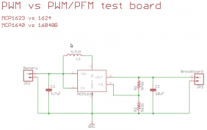
The design is just the reference design from the datasheet.
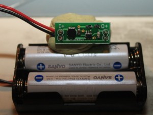
Here it is, finished, attached to a 2xAA battery pack. I quite like how easily it can also plug into a breadboard power supply rails.
Now, to solder up another one, and actually get the comparisons done!
Costs and parts (mine, you can easily subsitute):
| Part (@Mouser) | Cost (singles) |
|---|---|
| MCP1623/MCP1624 | 0.429€ |
| 0805, 10uF capacitor | 0.231€ |
| 0805, 4.7uF capacitor | 0.19€ |
| 0805 1% resistor, 976K | 0.035€ |
| 0805 1% resistor, 562K | 0.066€ |
| 4.7uH power inductor, about 1A rated | 0.437€ |
Total cost: 1.38 €. Compared to about 0.65€ or so for using a LDO and two capacitors. Better choices and sourcing for the capacitors and inductor would probably make a big difference.
Note: the MCP1640 family is rated for about 350mA for 3.3V output with 2xAAs, the MCP1623 and 1624 are rated to only 175mA, but that’s more then enough for my needs.
Eagle board/schematic files, as well as gerbers are available in my project space over at github

