Category Archives: wireless

Simplicity Studio 5 on Fedora 34

UPDATE: You can do the steps below, and it will…. mostly work, but you’ll still run into broken things like, unable to enter text on the project config wizards or the bluetoot gatt configuration. The only _viable_ solution I’ve found really, is just to log out, and log in again choosing “Gnome on Xorg” and just not making wayland part of your daily headaches.


You still need the export GDK_BACKEND=x11 trick, and you still need the ./studio -Djxbrowser.chromium.dir=/home/$USER/.jxbrowser trick.

You also need to make sure you have git-lfs installed, or you will get fun errors like

/home/karlp/Downloads/SimplicityStudio_v5/developer/toolchains/gnu_arm/10.2_2020q4/bin/../lib/gcc/arm-none-eabi/10.2.1/../../../../arm-none-eabi/bin/ld:/home/karlp/SimplicityStudio/SDKs/gecko_sdk//protocol/bluetooth/lib/EFR32BG22/GCC/binapploader.o:1: syntax error

$ cat /home/karlp/SimplicityStudio/SDKs/gecko_sdk//protocol/bluetooth/lib/EFR32BG22/GCC/binapploader.o
version https://git-lfs.github.com/spec/v1
oid sha256:59b50942a2f0085fe2c87d0d038b13b8af279c742f0d3013b1d1ad6929070a3f
size 66088

Oops, that doesn’t look like a bootloader binary! This is actually mentioned on https://docs.silabs.com/simplicity-studio-5-users-guide/latest/ss-5-users-guide-overview/known-issues as issue 76584, but you wouldn’t find that til later. The tips are to reinstall, but you can also

cd ~/SimplicityStudio/SDKs/gecko_sdk && git lfs fetch && git lfs pull && echo "whew, that took aaaages"

You can _probably_ do tricks with git lfs to just pull the single files you need, and avoid pulling the 800meg or something at 1meg/sec that it took, but this got me a building and functional simplicity studio! wheee…..

Sniffing 802.15.4 with wireshark and MRF24J40 modules

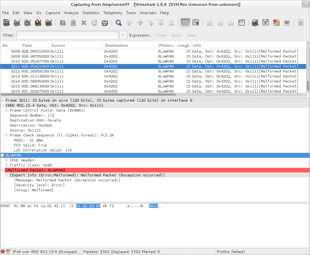
Wireshark screenshot showing my test data

This is what I did the last two evenings or so. The data being sent is from my example app for my MRF24J40 module library, simrf.

The streaming into wireshark is all thanks to one of the Contiki devs, George Oikonomou’s sensniff project. The peripheral code is just another app using my library.

Neat! This should make some things a bit easier to understand as I move into getting the full networking stack working in Contiki. (You can ignore the warnings from wireshark about the packets being invalid 6LoWPAN frames, all the frames are just raw 802.15.4, with “abcd” being sent as the frame payload.

Revised MRF24J40 driver code for STM32 and AVR

I meant to post this a while ago, but oh well :) A long time ago I made a basic driver for AVR, then I hacked it up a bit to make it run on the STM32L discovery board. None of the code was common, and the STM32 code was some of my earliest steps in that world. Last summer I started trying to put this all together, but I got busy with other things, and more particularly, I ditched the ST Standard Peripheral Lib and started actively working on libopencm3. Anyway, I eventually got back into project mode, and decided it was time to tidy this all up.

So, here it is. The 3rd edition of my MRF24J40 code. This one should be somewhat more portable to other platforms, as it uses function pointers to set up all the spi and interrupts. (As if anyone else is using this stuff anyway!)

https://github.com/karlp/simrf

There’s still plenty of tidying up that could be done, there always is, but it’s more going to be a base for further work on Contiki, so it’s probably about as good as it’s getting for now.

Porting Contiki to the STM32L

WARNING – rambling diatribe that might help me….

This is mostly a notepad of what I did, why I think I did it, and what I couldn’t find documented anywhere obvious at the time of writing

Motivation: I am interested in low power wireless sensor nodes. Most of the commonly used MCU operating systems I had looked at treated power usage as a second class citizen at best (if at all) Contiki builds all that in, it’s a primary concern. I abhor the idea of custom wireless protocols (even though I hacked one up for the current nodes in my house) Contiki builds in IPv6 (amongst other protocols) and knows explicitly about 802.15.4 (what I like to use) IP all the way sounds like a pretty smart bet.

So, I want to use contiki on my devices.

Right, big blob of unknown new code. What do I need, where does it need to go…. There’s a rather ugly blob of code in the repository that supports the STM32W series (a rather awkward part to use. No reference manual, binary blobs of radio drivers, the complete inability to order them to Iceland thanks to arbitrary export encryptions, etc) so maybe it would be easy. The code makes no real sense, and seems to be completely abandoned. There’s meant to be ARM support though, so shouldn’t be too hard.

Hrmm. code is split between “cpu” and “platform” Hard to know what should be where.
Oh! Someone just added support for the stm32F1, a chip I know well, no radio driver yet, but that’s ok, I know the MRF24J40 radio well, and would be using that anyway.

Oh, that code got reverted due to (to me) a fairly arbitrary lpgl vs bsd arguments (despite the stm32w code having a binary blob radio driver, let’s not start in there)

Ok, so, nothing says I can’t have my own fork, at least while licensing is worked out. https://github.com/contiki-os/contiki/wiki/Out-of-Tree-Development is the best reference I’ve found for getting started so far.

Now, I’ve got the hello world “app” copied into my tree as “foo” and I can do “make” and then ./foo.native and it works.

 karlp@tera:~/src/kcontiki (master *)$ ./foo.native 
Contiki 2.6 started
Rime started with address 2.1
MAC nullmac RDC nullrdc NETWORK Rime
Hello foo world
^C

Excellent, now what? Now I start to leave the comfort of the directions. I decide to copy the reverted stm32f107_basic platform into my tree, still following the Out of Tree Development guide

I’ve added libopencm3 as a git submodule too now. I can do “make TARGET=stm32ldiscovery” and it sort of works, in that it finds platforms/stm32ldiscovery/Makefile.stm32ldiscovery. Now I just need to know what _else_ is needed to go into that makefile. What’s in it now? MCK=72000000, do I really need that? I’d like to not have to care in a makefile. Hrmm. I guess what is really next is sorting out what is part of cpu/arm/xxx and what goes into platform/stm32ldiscovery.

CONTIKI_TARGET_MAIN. What’s that for? why do I need that? grepping the source shows totally inconsistent usages of it. Let’s ignore that for now.

Ok, the libopencm3 based stm32f107basic tree has a uart driver and some newlib stubs. Let’s keep as much of that as possible, and just hack the uart driver to be L1 based rather than F1 based. (This is actually just a difference in gpio AF function settings, the uart code is all identical)

That seems to get a little further, but now we need to get the cpu/arm/stm32f1x_cl code to work out somehow. let’s see how much of that is really “platform” Ok clock.c is opencm3 specific, but not f1x specific. OH! Here’s the MCK setting being used. ok, we’ll set that. rtimer* and mtarch* are all stubs, so that’s ok for now too.

So, a bit more hacking on the cpu/arm/stm32f1x_cl makefile to make it a little more of a “stm32 libopencm3” makefile, and we have a build!

But… does it work? No. setvbuf goes straight into the blocking handler, and puts does too. I guess something didn’t get linked or built properly. But we’re getting somewhere. I’ll look at the backtrace a bit later on, but it’s late.

Code so far in

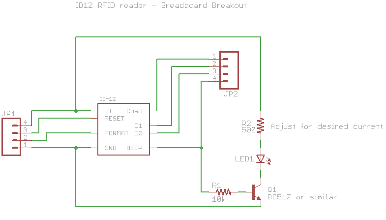
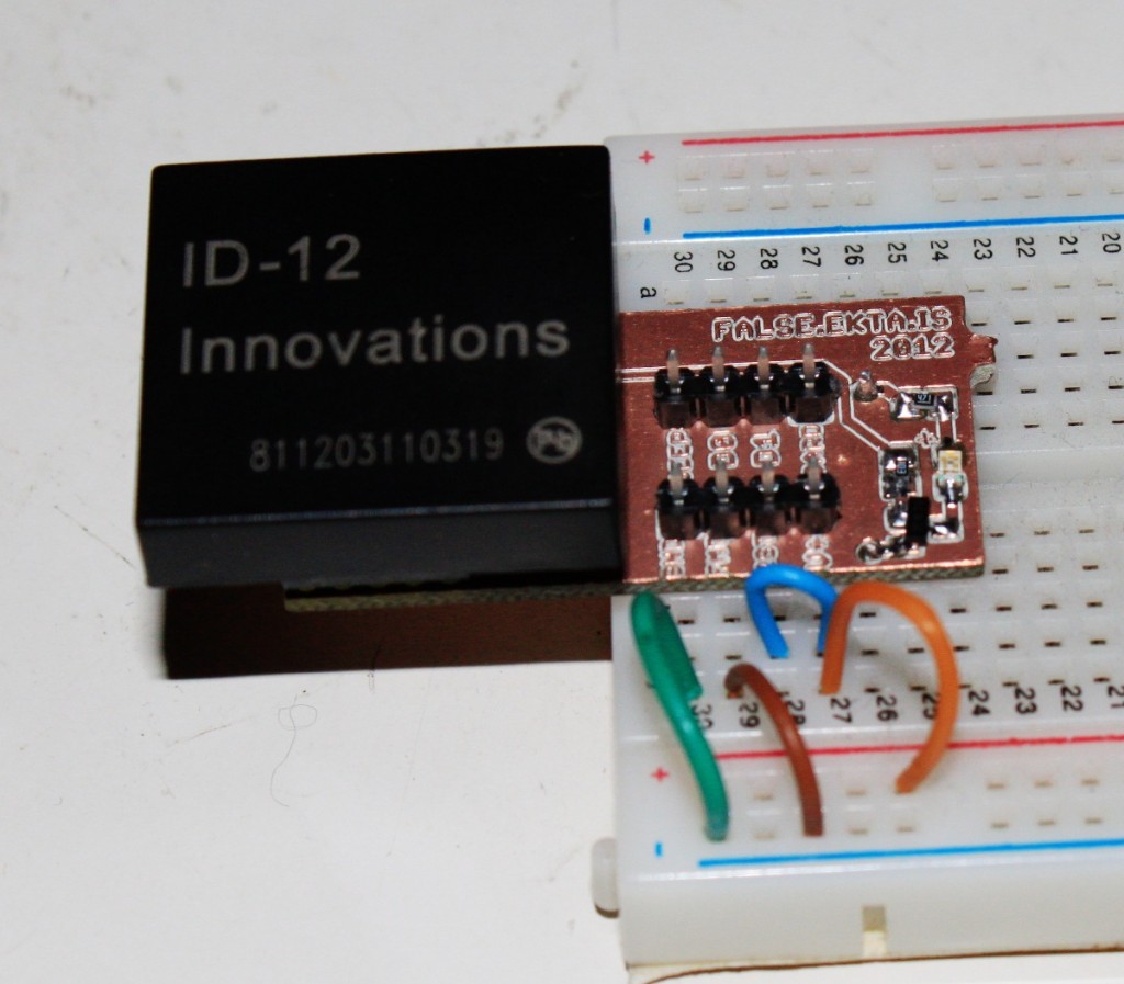
ID12 RFID breakout board

Some time ago I got an ID12 RFID reader module from Sparkfun, during their free day. I had some 2mm socket headers lying around from an xbee project, and finally got around to trying this thing out. Sparkfun sells a “breakout”, but in my mind it’s a bit of a failure, as it takes up too much space for easily mounting on a breadboard.

So, I made my own.
ID12 RFID Breadboard friendly breakout

I integrated the LED indicator of a successful read onto the board, and only the useful headers for the ID12 and ID20 modules. It’s much narrower, so easier to use on a breadboard. My board is only ~39mm x 19mm, designed to fit over the channel on a regular breadboard, yet still leave space for plugging wires in. Sparkfun’s is 25mm x 25mm. There’s not much too the design really,

This board was laid out to be made on a milling machine, so there’s no silkscreen text, it’s all in the copper layer instead, and it avoids assuming plated through holes, but it would work just fine manufactured normally. The LED circuit is surface mount, but you can ignore that completely by just not populating those parts.

You can get the eagle files in my github repository

Consider the license to be public domain, or your choice of BSD/MIT/X11.

I’ve only found one RFID card in my wallet that it can actually read, turns out there’s more rfid standards than I thought!

MRF24J40 driver for STM32

A while ago I put together a C driver for the MRF24J40 802.15.4 modules from microchip. I had been using them as a cheap alternative to xbees in some AVR projects. As I’ve been moving on to STM32 parts for hobby projects, (more power, cheaper) I started off porting my driver code from AVR over to cortex m3.

This has been quite an experience. The arm toolchain experience, and particularly the libc support and general documentation is completely different to, say, avr-libc (AVR-libc is a great project, reallly solid)

However, with lots of learning, and lots of mistakes, I’ve got it all working. It’s a first cut, but the basic features are there. There’s no magic for DMA, and you have to do a lot of the pin setup yourself, but this is Cortex M3, there’s so many pins you could be using for this! I’ve tried to reduce the required function calls as much as possible, but there’s still room for improvement.

    // Required by the user code
    extern void mrf_select(void);  // Chip select, if necessary
    extern void mrf_deselect(void);  // chip deselect, if necessary
    extern uint8_t spi_tx(uint8_t cData);
    extern void _delay_ms(int);  // only used at init time.

This still needs to move to a clear sub project, currently it’s a separate code base to the AVR code.

Get the code now!

More to come, as it gets tidied up and put into use!

Updated MRF24J40 arduino driver

Thanks to pkarck my changes to improve the C library for Microchip’s MRF24J40 802.15.4 modules has been ported to the Arduino library. I’d written an Arduino library some time ago, but hadn’t been maintaining it as I don’t really deal with Arduino much these days. However, it’s gotten some love :) It’s now easier to use, and has support for the power amplifier on the MRF24J40MB modules, if you’re using those. It also makes some quirks I was dealing with in a mixed xbee/mrf24j40 module environment optional. In general, this collects up some of the various reported issues over the last year or so, and I didn’t have to do anything at all!

This is, “teh awesome”.

Downloads:

Fridge Controller – temperature and motor run time, reporting over 802.15.4

One of my most finished projects, mostly because it’s simply much more important than having a battery powered thermometer sitting on a shelf. I brew beer, and serve beer in a converted fridge in my loungeroom. One day, the beer got slow, and what came out was suspicously cold. Turns out the thermostat was broken, so as long as the fridge had power, it was cooling, which resulted in deeply frozen kegs of beer.

It’s a pretty old fridge, that I got free, so I thought about simply getting a new (second hand) fridge and doing the conversion again. A newer fridge would probably be quieter, use less energy, all good things. But, not all fridges are the same shape, and finding one that fit three kegs, and doing all the work of the conversion again just felt like a lot of work. And goddamnit, I’ve been building sensor nodes, I always planned on having nodes that could control things too, so maybe I should just get down to business.

In the end there wasn’t much too it. I’m not doing any fancy PID control, just a set point, and a minimum motor run time, and minimum motor rest time. Initially, it didn’t even listen to any controls from my network, it reported temperature and motor status, but that was it. I had no beer! This was too important to have offline for weeks while I played around 24-480

I got a (massivly overspecced) 25A SSR on ebay, and after a bit of thought about how to keep the cost down, came up with the following schematic:
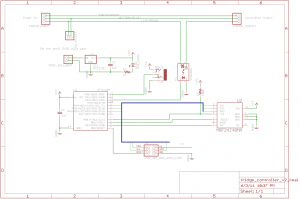
Full schematic for the fridge controller

The clever bit, if I can call it that, was to not even think about making my own power supply for the control logic. Big companies can make 10 gazillion CE marked, compact, safe switch mode power supplies, and consumers can throw them out by the gazillion. I was just going to have a normal euro 2 prong socket, and a surplus phone charger plug pack with the jack cut off and soldered to the board. Presto, cheap _and_ safe. Far far cheaper, faster and easier than I could have done myself. Of course, the extra socket and jacks take up space, but you can only have so much cake.

There’s really not an awful lot more to it than that. I tested this with a teensy board first, because I could use the nice friendly USB port for debugging, then switched to the ATtiny84, and after a bit of fiddling to get USI working for SPI, it all “just worked” I was suitably impressed when the fridge turned on and off at the right times :)

If you want to make this cheaper, you can just drop the 802.15.4 radio altogether. It worked well enough to keep my beer cold but not frozen before I finished the code to listen for new parameters over the air. But, being able to tweak it’s settings is a nice thing.
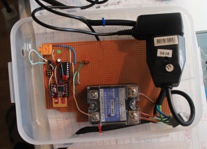
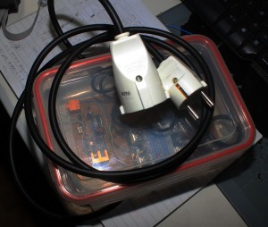
The TMP36, or similar, is wired up on a chopped up length of headphone cable. This is the bit that’s easiest to get wrong. Take care with the pinouts of whatever headphone socket you use, and the way you wire which lead to which part of the 3.5mm stereo plug. (If you get it wrong, you’ll read temperatures like 50, then 80, then 90 degrees Celsius, which will actually be _correct_ if you touch the sensor!)

Things I would have liked to have done:

  • Make the headphone socket mount flush on the wall of the box. Just takes more money and time to get the mounting perfect.
  • Use a panel mount socket for both input and output. It would be much tidier, but it takes yet more space, and yet again, more money

Other notes

The SSR I got really needs 3V+ to control. I was mistakenly feeding it with about 2V, from the wrong side of a resistor divider, early on in testing, and the red LED on the device would light up, so I expected it to properly be switching the live side. However, it seems 2V was enough for the LED, but not enough to actually switch. As soon as I gave it 3V, it behaved perfectly.

There’s no LCD display. Which might have been nice, but really, how often do you look at the temperature of your fridge? Besides, because it’s reporting every 10 seconds to “karlnet” it becomes just another node that the rest of my system stores in databases, graphs, or uploads to pachube

The software has a fairly nice way of working with saved state in EEPROM I learnt recently. I’m quite happy with it :) However, in general, the code is a little bit harder to read, because it contains all the debug for a teensy board, with #defines separating the live code from the test code. This is however a fully fledged real demo of my updated MRF24J40 library code

Downloads

Parts list below.

Part

quantity

price

supplier

25A SSR, 3-25V control, 24-480VAC output

1

7.99 US

ebay

grounded euro socket

1

195 ISK

Byko

grounded euro plug

1

195 ISK

Byko

Ungrounded euro socket

1

181 ISK

Byko

3 strand power cable

2m

363 ISK

Byko

lunch box

1

499 ISK

Húsasmiðjan

Green LED

1

0.05€

Mouser

ATtiny84

1

2.39€

Mouser

MRF24J40MA

1 (optional)

7.46€

Mouser

3.5mm stereo socket, board mount

1

0.44€

Mouser

MCP1702, 3.3V regulator

1

0.39€€

Mouser

TMP36

1

1.58 US

Digikey

1uF capacitors

2

0.40€

Mouser

5V DC plugpack/wallwart

1

500 ISK

Second hand store

2×3 pin header for AVR programming

1

sockets and header pins to comfort

?

?

?

The mouser parts should be available as Shared project 3411228a84 You can substitute something else for the TMP36, that’s just what I had wired up.

Because remember, Digikey are evil, and still refuse to recognise that the 802.15.4 encryption was removed from export restrictions years ago. Digikey, in their infinite wisdom REFUSE TO SHIP 802.15.4 modules to Iceland. We’re terrorists or something.
Updated MRF24J40 library code, now easier to use

I’ve just substantially updated my library code for dealing with Microchip’s MRF24J40 modules on AVR microcontrollers, making it much much easier to use. It’s now based on callbacks for handling rx/tx packets, so you don’t need to know anywhere near as much about the module’s internals anymore. The tradeoff is a bit more ram usage.

mrf_reset and mrf_init now take parameters to ports and pins, so you no longer need to mess around with defines in the library headers any more.

#include "lib_mrf24j.h"
    mrf_reset(&PORTB, PINB5);   // reset pin
    mrf_init(&PORTB, PINB0);  // chip select pin

You no longer need to manually work with the interrupts, you just need to set up the ISR for the pin you’ve chosen to connect to the MRF24J40’s INT pin, for example, for my case, using INT0. (Remember to add a EIMSK |= _BV(INT0); somewhere too!)

ISR(INT0_vect) {
    mrf_interrupt_handler();
}

The interrupt handler takes care of reading in received rf data, and keeping it in a local buffer. It always contains the most recent packet. To do something with the received data, call mrf_check_flags() pretty often. It takes two function pointers as parameters, one which will be called for rx, and one for tx. Here’s a snippet from my main().

    // set the pan id to use
    mrf_pan_write(0xcafe);
    // set our address
    mrf_address16_write(0x6001);
    while (1) {
        // Call this pretty often, at least as often as you expect to be receiving packets
        mrf_check_flags(&handle_rx, &handle_tx);
        if (time_to_send()) {
            mrf_send16(0x4202, 4, "abcd");
        }
    }

And here’s some example rx/tx callback handlers.

void handle_rx(mrf_rx_info_t *rxinfo, uint8_t *rx_buffer) {
    printf_P(PSTR("Received a packet: %d bytes long\n"), rxinfo->frame_length);
    printf_P(PSTR("Packet data:\n"));
    for (int i = 0; i <= rxinfo->frame_length; i++) {
        printf("%x", rx_buffer[i]);
    }
    printf_P(PSTR("\nLQI/RSSI=%d/%d\n"), rxinfo->lqi, rxinfo->rssi);
}
 
void handle_tx(mrf_tx_info_t *txinfo) {
    if (txinfo->tx_ok) {
        printf_P(PSTR("TX went ok, got ack\n"));
    } else {
        printf_P(PSTR("TX failed after %d retries\n"), txinfo->retries);
    }
}

The library code is available here, and also on github (lib_mrf24j)

Complete demo code for a module connected to a PJRC Teensy 2.0 board is here and also on github (You’ll probably have to edit paths in the Makefile)

Dresden Elektronik ATmega128RFA1 breakout boards, deRFmega128

I’ll write up more about the parts themselves later, but I finally got boards made for Dresden Elektronik’s deRFmega128 modules, both made, and now assembled and tested. Briefly, these are a module with Atmel’s ATmega128RFA1 (a combined ATmega128 with a 802.15.4 2.4 Ghz transceiver on a single chip) with either a chip antenna, or a connector for your own antenna. These are TINY, and they also manage to pack a 1Mbit EEPROM on the module, for your own use. All for 21€

I’ve only tested a basic blinky thing so far, but it’s good to know that I can finally start doing something with these cool modules.

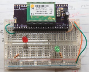
Here’s one up on a breadboard.

These modules are the same length as PJRC’s Teensy boards, but they have leads on 1.27mm pitch, not 2.54mm pitch. Lots more pins, but you’ll need some parts. For the 1.27mm socket holders, I ordered direct from Samtec. [1] Dresden recommends SLM Series, but I ordered SMS series. It may have been price, or availability, who knows. I ordered SMS-123-02-G-S, and the pins are really way too long on those. SMS-01-G-S would have been a better choice. Also, and I don’t know if the SLM would have been better, but I have a little bit of a hard time getting the modules into these sockets. They seem to “spring” out a little bit, to point that I initially thought I had failed to make my pcbs properly. Some of the pins weren’t making good contact. I have my modules mounted “upside down” with the silver RF can facing down. That’s the way the module leads are longest, and gold, and the only way they fit, when I was testing out the sockets and the modules. (Before the boards got here)

I’ve now found, that they will fit in nicely with the metal can UP and click into place nicely, but that’s not pin compatible with the AVR ISP header, or the power supply I put on the breakout.

So, I have some breakouts that work just fine, if you solder the part in, and probably well enough for development before your own boards, but I’m probably going to respin them :( The modules are cool, and they just came out with a pin compatible module, with an ARM7 core, instead of the ATmega128.

I still have a spare board from this revision though, if you are at all interested, I can send you one :)

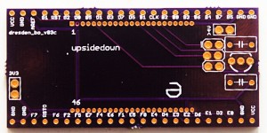
Here’s the board itself

Note, it already says rev3. That’s a story for another day :)

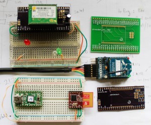
And to leave you, a picture of the different RF modules I’ve been working with here recently.

deRFmega128, Teensy v2 + MRF24J40MA, Xbee Series 1 + adafruit board

The current board files are available from https://github.com/karlp/karlnet/tree/master/experiments/dresden

The very basic blinking demo is also at github, should you really want it :)

[1] You can pretty much forget about getting 23pin headers from either digikey or mouser. Samtec were prompt, and had cheap enough shipping, relatively speaking. (I ordered a dozen)