Category Archives: software

Early impressions with PyDev 2.2 and Eclipse 3.7

I’ve been happily using netbeans for C/C++ and python work, which works well enough to not really complain much. Mostly, I want IntelliJ for C code. I find eclipse big and clunky and awkward on the keyboard, and just generally a pain. No Eclipse, I do NOT want to have some sort of “workspace” I want you to just leave things where they are on the disk. Anyway, in Oracle’s infinite wisdom, they are continuing to destroy things that Sun built, and python support has been dropped in netbeans 7. A pity, as netbeans 7 added some nice debugging support for C/C++, and netbeans is much more tightly integrated than eclipse. Still a pale shadow of IntelliJ, but I digress.

So, I had to go and look for some alternative python editors. I’m currently trying out PyDev 2.2 with Eclipse 3.7. It mostly works ok too. It’s capable of running some unit tests, and has the basic highlighting and so on. However, it’s completion is not as good as I would like, nor think it should be. Take this for example.

def something(self):
    self.mylist = []
    # on this line, self.mylist. will give me the full builtin completion for lists
    self.otherlist = "blah blah".split()
    # split returns a list, but self.otherlist. has no completion here

It seems this can be worked around by “pre declaring” the type.

def something(self):
  self.somelist = []
  self.somelist = "blah blah".split()
  # self.somelist. produces full completion for list here....

This is…. odd?

Possibly related is that in python unit tests, I at least, normally use the self.assertEquals(left, right, msg) form, probably because I came from Java. However, self.assertEquals in PyDev doesn’t give me any completion guidance on the parameters at all. It turns out that in the implementation of python’s unittest, assertEquals is simply an alias for another function (assertEqual = assertEquals = failUnlessEqual) For whatever reason, this means that I get full completion and parameter help if I use the _real_ implementation, failUnlessEqual but no advice/help whatsoever if I use the assertEquals form.

Google says this is unhelpful.

  • “self.assertEquals python” returns 74300 results
  • “self.failUnlessEqual python” returns 35800 results

Update: this assertEquals vs failUnlessEqual is apparently only a problem for python < 2.7. Unfortunately debian stable (squeeze) at present still uses python 2.6 :( In more mundane items, I would _really_ like to know how to get IntelliJ's "ctrl-W" shortcut, for expanding a selection. (From the cursor in the middle of "karl" in the following line, 'self.wop = "this is karl in python".split()', pressing ctrl-w once would highlight 'karl', once more would select 'this is karl in python' (without the quotes), once more with the quotes, and then on to the entire rvalue, then the entire line. This stackoverflow post mentions a solution, but it doesn’t seem to work in PyDev windows, even after getting into the keymap and adding a “Select Enclosing Element” for the PyDev views (or the editor scope? the difference being?) it still doesn’t work.

Oh well, life goes on.
Public key encryption of MQTT messages, with C and python

WARNING Don’t do this. It does work, but you are limited to sending messages that are smaller than the public key size less padding bytes. The “correct” way is to use the higher level EVP_SealXXXX and EVP_OpenXXXX methods. (which are substantially uglier, but are “the right thing”™ I’ll try and package up some sample code in the neart future

As a follow on from yesterday, where we simply signed the message body being sent to the MQTT server, today we will use public key encryption to secure the message bodies themselves. For an environment where multiple people are connected to the MQTT server, but only one of them is authorized to be reading all the data, this seems a nice way of doing it. We don’t care if any given client is compromised, they only get our public key.

First off, I was less than impressed with the state of the public key encryption/decryption code in python. There’s nothing in the standard library, and PyCrypto doesn’t support reading in standard openssl key files, so I didn’t even bother looking much further. KeyCzar promises to be useful, doing “the right thing” instead of forcing you to know everything about crypto yourself. (I resent having to read the docs closely enough to make sure I chose PKCS_OEAP padding, rather than just PKCS padding for the RSA encryption. I do NOT want to be a crypto guy, and I know that I will never know enough) However, KeyCzar also insists on doing it’s own key management, so I moved on. M2Crypto seems to be the most fully implemented, but, unfortunately, it keeps the terrible/wonderful OpenSSL API. I’m using OpenSSL in the C code, so at least it’s consistent, even if it is a terribly verbose and awkward API.

Other things that I learnt were important, in the C code.

  • Remember to call XXX_free() on OpenSSL objects that are created. (such as RSA keys from PEM_read_bio_RSA_PUBKEY)
  • Remember that openssl calls to encrypt can only encrypt clear text less than a certain size. (256 bytes in my case)
  • Remember that the limit on clear text size does NOT account for padding sizes! RSA_size(key) returns the total size, but with the recommended RSA_PKCS1_OAEP_PADDING the overhead is 41 bytes!

The heart of the C encryption side:

int encrypt_message(unsigned char **encrypted, unsigned char *clear, uint32_t clear_len) {
    RSA *pubkey = rsa_get_public_key();
    int rsa_size = RSA_size(pubkey);
    assert(clear_len < rsa_size - 41);  // 41 is the padding size for RSA_PKCS1_OAEP_PADDING
    ILOG("rsa size = %d\n", rsa_size);
    *encrypted = malloc(RSA_size(pubkey));
    uint32_t encrypted_len = RSA_public_encrypt(clear_len, clear, *encrypted, pubkey, RSA_PKCS1_OAEP_PADDING);
    RSA_free(pubkey);
    if (encrypted_len == -1) {
        fatal("Failed to encrypt data. %s", ERR_error_string(ERR_get_error(), NULL));
    }
    return encrypted_len;
}

rsa_get_public_key() is some openssl gloop code that you should replace, it provides a hard coded public key I generated yesterday for some tests.

The python decryption code is even simpler:

    # This keyfile has had the passphrase removed....
    private_key = M2Crypto.RSA.load_key("/home/karlp/karl.test.private.nopf.key")
    clear_text = private_key.private_decrypt(payload_bytes, M2Crypto.RSA.pkcs1_oaep_padding)
    log.info("Decrypted message: <%s>", clear_text)

You can get the code:

Update: The first edition of this post referred to problems with easily getting the binary payload from the MQTT message. This has since been solved, and will be integrated into a future release of mosquitto.

MQTT dissector / decoder for Wireshark

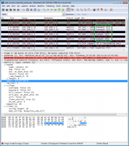
While debugging some problems we were having with TCP performance, I wanted a way to visualize the MQTT traffic stream a little better in wireshark. I found Wireshark Generic Dissector and thought it should be useful, seeing as I had no desire to start writing C code for packet decoding. WSGD looks to be pretty interesting for writing decoders for private protocols and the like, but there aren’t many other examples of how it’s used. I got helpful prompt help from the lead developer though, so even though it’s a little arcane, it’s still something I can recommend :)

MQTT decoding in Wireshark through WSGD

MQTT decoding in Wireshark through WSGD

My decoding isn’t complete, by any means, but given the complete lack of any other examples out there, I thought this would probably be helpful, even in it’s current state. You’ll need to install WSGD as per the instructions at that site, and then you’ll need this zip….

Just follow the instructions here and by all means, let me know how you go :)

Update: 2014-02-01: There’s an alternative lua plugin, available on github. I haven’t tried it, but lua plugins are actually easier to use and extend. If I’d know about the lua plugin style (and known lua) at the time, I would have done it that way. Note, I haven’t actually _tried_ the lua plugin yet :)

Everything that is wrong with Arduino

Everything that is wrong with Arduino can be summed up with this enhancement request: Way to specify number of digits / places when printing hex, octal, and binary numbers.

Fridge Controller – temperature and motor run time, reporting over 802.15.4

One of my most finished projects, mostly because it’s simply much more important than having a battery powered thermometer sitting on a shelf. I brew beer, and serve beer in a converted fridge in my loungeroom. One day, the beer got slow, and what came out was suspicously cold. Turns out the thermostat was broken, so as long as the fridge had power, it was cooling, which resulted in deeply frozen kegs of beer.

It’s a pretty old fridge, that I got free, so I thought about simply getting a new (second hand) fridge and doing the conversion again. A newer fridge would probably be quieter, use less energy, all good things. But, not all fridges are the same shape, and finding one that fit three kegs, and doing all the work of the conversion again just felt like a lot of work. And goddamnit, I’ve been building sensor nodes, I always planned on having nodes that could control things too, so maybe I should just get down to business.

In the end there wasn’t much too it. I’m not doing any fancy PID control, just a set point, and a minimum motor run time, and minimum motor rest time. Initially, it didn’t even listen to any controls from my network, it reported temperature and motor status, but that was it. I had no beer! This was too important to have offline for weeks while I played around 24-480

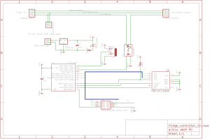
I got a (massivly overspecced) 25A SSR on ebay, and after a bit of thought about how to keep the cost down, came up with the following schematic:

Full schematic for the fridge controller

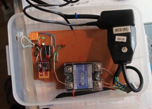
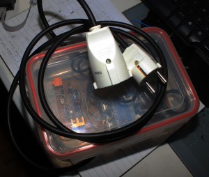
The clever bit, if I can call it that, was to not even think about making my own power supply for the control logic. Big companies can make 10 gazillion CE marked, compact, safe switch mode power supplies, and consumers can throw them out by the gazillion. I was just going to have a normal euro 2 prong socket, and a surplus phone charger plug pack with the jack cut off and soldered to the board. Presto, cheap _and_ safe. Far far cheaper, faster and easier than I could have done myself. Of course, the extra socket and jacks take up space, but you can only have so much cake.

There’s really not an awful lot more to it than that. I tested this with a teensy board first, because I could use the nice friendly USB port for debugging, then switched to the ATtiny84, and after a bit of fiddling to get USI working for SPI, it all “just worked” I was suitably impressed when the fridge turned on and off at the right times :)

If you want to make this cheaper, you can just drop the 802.15.4 radio altogether. It worked well enough to keep my beer cold but not frozen before I finished the code to listen for new parameters over the air. But, being able to tweak it’s settings is a nice thing.

The TMP36, or similar, is wired up on a chopped up length of headphone cable. This is the bit that’s easiest to get wrong. Take care with the pinouts of whatever headphone socket you use, and the way you wire which lead to which part of the 3.5mm stereo plug. (If you get it wrong, you’ll read temperatures like 50, then 80, then 90 degrees Celsius, which will actually be _correct_ if you touch the sensor!)

Things I would have liked to have done:

  • Make the headphone socket mount flush on the wall of the box. Just takes more money and time to get the mounting perfect.
  • Use a panel mount socket for both input and output. It would be much tidier, but it takes yet more space, and yet again, more money

Other notes

The SSR I got really needs 3V+ to control. I was mistakenly feeding it with about 2V, from the wrong side of a resistor divider, early on in testing, and the red LED on the device would light up, so I expected it to properly be switching the live side. However, it seems 2V was enough for the LED, but not enough to actually switch. As soon as I gave it 3V, it behaved perfectly.

There’s no LCD display. Which might have been nice, but really, how often do you look at the temperature of your fridge? Besides, because it’s reporting every 10 seconds to “karlnet” it becomes just another node that the rest of my system stores in databases, graphs, or uploads to pachube

The software has a fairly nice way of working with saved state in EEPROM I learnt recently. I’m quite happy with it :) However, in general, the code is a little bit harder to read, because it contains all the debug for a teensy board, with #defines separating the live code from the test code. This is however a fully fledged real demo of my updated MRF24J40 library code

Downloads

Parts list below.

Part

quantity

price

supplier

25A SSR, 3-25V control, 24-480VAC output

1

7.99 US

ebay

grounded euro socket

1

195 ISK

Byko

grounded euro plug

1

195 ISK

Byko

Ungrounded euro socket

1

181 ISK

Byko

3 strand power cable

2m

363 ISK

Byko

lunch box

1

499 ISK

Húsasmiðjan

Green LED

1

0.05€

Mouser

ATtiny84

1

2.39€

Mouser

MRF24J40MA

1 (optional)

7.46€

Mouser

3.5mm stereo socket, board mount

1

0.44€

Mouser

MCP1702, 3.3V regulator

1

0.39€€

Mouser

TMP36

1

1.58 US

Digikey

1uF capacitors

2

0.40€

Mouser

5V DC plugpack/wallwart

1

500 ISK

Second hand store

2×3 pin header for AVR programming

1

sockets and header pins to comfort

?

?

?

The mouser parts should be available as Shared project 3411228a84 You can substitute something else for the TMP36, that’s just what I had wired up.

Because remember, Digikey are evil, and still refuse to recognise that the 802.15.4 encryption was removed from export restrictions years ago. Digikey, in their infinite wisdom REFUSE TO SHIP 802.15.4 modules to Iceland. We’re terrorists or something.

PetitFatFs SD card bootloader for ATmega2560 / Arduino Mega 2560

ChaN’s PetitFatFs, is a pretty neat plain C library dealing with Fat file systems (like on SD cards) with as little code as possible. It even includes sample bootloader code for AVR, which tries to open a file on an SD card, and if it exists, write it to flash, before booting the user application.

It’s a pretty neat base, though you may/probably will want to add a little bit functionality. The directions that come with the code are pretty good for getting this working. [1] However, for boards based around the ATmega2560, or ATmega2561, which contain >128k program space, a couple of things just don’t work…

First, the code for jumping into the user code:

    ((void(*)(void))0)();

This is fairly commonly seen pattern, but least with GCC 4.3.3 (WinAVR 20100110) this generates incorrect code. It gets turned into an EICALL, but without setting EIND. This results in the bootloader continually resetting into itself. (And, if the file on the sd card exists, repeatedly overwriting flash as fast as possible, not really very good for your flash lifetime!)

The alternative, which correctly generates a jump to the real 0, (These big ATmega’s have a 22 bit Program Counter, not a 16 bit one) is simply:

    asm volatile("jmp 0000");

The other required piece of the puzzle, is actually an AVR-libc FAQ item. You need to add -mrelax to your linker options.

As best I can tell, both of these additions should actually “do no harm” for regular sized AVRs as well, but I don’t have any boards handy to try that out with.

By the way, if you’re using the SD card on an arduino ethernetshield, below is the the only change you need in asmfunc.S. Just to save you from working out what the real name for “digital pin 4” is C land.

#define	DDR_CS	_SFR_IO_ADDR(DDRG), 5	// MMC CS pin (DDR, PORT)
#define	PORT_CS	_SFR_IO_ADDR(PORTG), 5

Now, if only I could convince avrdude to erase all the flash, but only program the 4-8kb of bootloader, instead of insisting that it needs to program the entire 256k of flash each time I make a tweak to the bootloader. (139 seconds to program using a FabISP)

[1] The only thing I found unclear at first was setting up the “DI” and “DO” pins. Given that I was choosing pins that were on my mega2560, I assumed these were Data Out and Data In, when seen from the point of view of the mega2560. They are not, they are from the point of view of the SD card. (This is actually shown on the schematic image that comes with the PetitFatFs sample download)

Updated MRF24J40 library code, now easier to use

I’ve just substantially updated my library code for dealing with Microchip’s MRF24J40 modules on AVR microcontrollers, making it much much easier to use. It’s now based on callbacks for handling rx/tx packets, so you don’t need to know anywhere near as much about the module’s internals anymore. The tradeoff is a bit more ram usage.

mrf_reset and mrf_init now take parameters to ports and pins, so you no longer need to mess around with defines in the library headers any more.

#include "lib_mrf24j.h"
    mrf_reset(&PORTB, PINB5);   // reset pin
    mrf_init(&PORTB, PINB0);  // chip select pin

You no longer need to manually work with the interrupts, you just need to set up the ISR for the pin you’ve chosen to connect to the MRF24J40’s INT pin, for example, for my case, using INT0. (Remember to add a EIMSK |= _BV(INT0); somewhere too!)

ISR(INT0_vect) {
    mrf_interrupt_handler();
}

The interrupt handler takes care of reading in received rf data, and keeping it in a local buffer. It always contains the most recent packet. To do something with the received data, call mrf_check_flags() pretty often. It takes two function pointers as parameters, one which will be called for rx, and one for tx. Here’s a snippet from my main().

    // set the pan id to use
    mrf_pan_write(0xcafe);
    // set our address
    mrf_address16_write(0x6001);
    while (1) {
        // Call this pretty often, at least as often as you expect to be receiving packets
        mrf_check_flags(&handle_rx, &handle_tx);
        if (time_to_send()) {
            mrf_send16(0x4202, 4, "abcd");
        }
    }

And here’s some example rx/tx callback handlers.

void handle_rx(mrf_rx_info_t *rxinfo, uint8_t *rx_buffer) {
    printf_P(PSTR("Received a packet: %d bytes long\n"), rxinfo->frame_length);
    printf_P(PSTR("Packet data:\n"));
    for (int i = 0; i <= rxinfo->frame_length; i++) {
        printf("%x", rx_buffer[i]);
    }
    printf_P(PSTR("\nLQI/RSSI=%d/%d\n"), rxinfo->lqi, rxinfo->rssi);
}
 
void handle_tx(mrf_tx_info_t *txinfo) {
    if (txinfo->tx_ok) {
        printf_P(PSTR("TX went ok, got ack\n"));
    } else {
        printf_P(PSTR("TX failed after %d retries\n"), txinfo->retries);
    }
}

The library code is available here, and also on github (lib_mrf24j)

Complete demo code for a module connected to a PJRC Teensy 2.0 board is here and also on github (You’ll probably have to edit paths in the Makefile)

FatFs with Arduino Mega 2560 and EthernetShield micro SD card

This is based on FatFs 0.8b, the latest release at the time of writing. We wanted to use the SD card slot on the standard arduino ethernet shield, and there’s a standard arduino provided SD library for working the sd card slot. However, despite the claims in the arduino FAQ, where it says, “… the C/C++ microcontroller libraries are under the LGPL” and “Using the Arduino core and libraries for the firmware of a commercial product does not require you to release the source code for the firmware. The LGPL does, however, require you to make available object files that allow for the relinking of the firmware against updated versions of the Arduino core and libraries. Any modifications to the core and libraries must be released under the LGPL.” this is actually untrue. Even on the SD card library reference page or Notes on using SD cards no mention is made of the fact that the SD library is actually GPLv3. Because the library is based on the GPLv3 sdfatlib

This is a pretty glaring omission, and a rather rude piece of code to just slip in.

Fortunately, there is also FatFs, and it’s tiny sister, PetiteFs, which are both under a BSD style license. They’re also plain C, and a lot more portable, with the sample code working on not just AVR, but ARM, i386, h8, and on and on.

So, I thought it should be possible to get that working with our mutant arduino here. Two websites were very useful in getting me started in the right direction, (in addition to the FatFs documentation)

What did I actually have to do?

  1. Download FatFs sample, and grab diskio.h, ff.c, ff.h, ffconf.h, integer.h and mmc.c and put them in my project
  2. Replace allll instances of BYTE with BYTEF (or anything else you want) in those files. BYTE is already defined (and differently) by the Arduino codebase
  3. In diskio.h, I had to add the following c++ wrapper
    #ifdef	__cplusplus
    extern "C" {
    #endif

    at the start, and close it at the end.

  4. Edited the ffconf.h to suit, (This is up to you…)
  5. in mmc.c, I added #include "WProgram.h"
  6. in mmc.c, I replaced the #defines for CS_LOW and CS_HIGH with digitalWrite(4, LOW/HIGH). For the Arduino Ethernet shield, chip select is on pin 4.
  7. in mmc.c, the three power_* functions were stubbed out. The ethernet shield doesn’t support this.
  8. in mmc.c, the disk_timerproc function had the write detect and card inserted logic removed, again, the ethernet shield doesn’t support this.
  9. in mmc.c, because I wanted write support, I had to provide a function, DWORD get_fattime(), which simply returns 1. This is the file create time, and if you don’t really care what timestamp you get, a fixed value is fine. You would normally hook this up to an RTC or something.

    That’s about it. Then, just be careful to make sure that SPI is set up properly (taken care of if you’re using the ethernet on the ethernet shield) and, very importantly, make sure to include pinMode(4, OUTPUT) to make sure that the SD cards chip select pin is actually an output. If you forget this, it will sometimes work, and sometimes fail, and be very very very unpredictable.

    Oh, And you need to set up a timer to call disk_timerproc() every 10ms. The circleofcurrent page shows how to work around this with fixed loops if you’d prefer, but I just set up Timer2 to do this. This list of arduino resources used seems to imply that Timer2 is safe for us, but your mileage may vary. Here’s how we set up Timer2

            TCCR2A = _BV(WGM21);  // CTC MODE
    	TCCR2B = _BV(CS22) | _BV(CS21) | _BV(CS20); // clkdiv 1024
    	TIMSK2 = _BV(OCIE2A);			/* Output compare match interrupt */
    	OCR2A  = 156;         // 156 ticks at 16Mhz/1024 = ~10ms
            // Needs to be turned on before we start trying to wake up the sd card!
    	sei();
            // fatfs disk init code below...

    This was all done on an Arduino Mega 2560 board.

Remember, chip select pins need to be outputs!

I was struggling with (very) unreliable file reads and writes while trying to get FatFs running on an Arduino Mega 2560 board, with the standard Arduino Ethernet Shield. The ethernet connection was continually dropping and reconnecting as well.

What was missing? I hadn’t set the pin used for chip select on the SD card to be an output. As soon as I added that, my file operations became 100% reliable, and my ethernet connection stopped bouncing. Excellent!

(I’ll try and package up what we needed to get FatFs working, but it might not be today)

avrdude 5.10, arduino mega 2560, command line uploading

Note: The following probably applies to the arduino UNO as well, as it also uses an onboard atmega 8u2, rather than the old raw serial converter.

Part 1 of probably many. I’ve inherited some arduino code, targetting the quite new mega2560 boards. You know, the ones that include an onboard atmega8u2, rather than the original old serial adapters. In many ways, this is a welcome step into the future. Anyway, this place doesn’t even have a regular AVR ISP programmer, and with the onboard real usb, the code running on the 8u2 is actually effectively an AVR ISP programmer itself, talking the stk500 protocol.

I am trying to move some of this code slowly out of the arduino IDE, and towards a more standard shared tree of c/c++. I have mostly succeeded in building plain hex files from the command line, based on arduino libraries (for things like LiquidCrystal and Ethernet and so on) but was having problems getting them to program. By editing arduino’s “preferences.txt” and adding “upload.verbose=true” I could see that when programming from the arduino IDE, it was using a private patched version of avrdude (5.4-arduino) with the programmer type of stk500v2, and that it was issuing a reset, via some sort of DTR toggle…


c:\tools\arduino-022\hardware/tools/avr/bin/avrdude -CC:\tools\arduino-022\hardware/tools/avr/etc/avrdude.conf -v -v -v -v -cstk500v2 -p atmega2560 -P COM5 -b 115200
... version stuff ...
Using Programmer: stk500v2
Overriding Baud Rate: 115200
avrdude: ser_open(): setting dtr
avrdude: Send: . [1b] [20] . [00] . [03] . [0e] . [11] . [01] . [01] ' [27]

Ok, so now I had enough to try and run it myself, using avrdude 5.10, as comes with recent versions of WinAVR


C:\Users\karlp>avrdude.exe -p atmega2560 -P COM5 -c stk500v2 -v -U lfuse:r:-:h -b 115200
---snip---
avrdude.exe: stk500_2_ReceiveMessage(): timeout

But, as you can see, this just timed out. Looking at the LEDs, I could see that the board wasn’t getting magically reset. With a bit of reading and searching, I found out that avrdude added a way of resetting the board, if you use the programmer type of “arduino”


Using Programmer : arduino
Overriding Baud Rate : 115200
avrdude.exe: Send: 0 [30] [20]

Interesting, following the lights on the board, I could see that this was now resetting properly, but clearly, those were not the right commands. It seems that the “arduino” programmer type, is set up to talk to the bootloader on the atmega328 of the prior versions of arduino, the Duemilanove and so on, that still had a direct USB-serial bridge, from the FTDI chip. So, if the “arduino” programmer does the reset, but the wrong protocol, looks like I’ll have to reset it myself.

I finally tried holding reset on the board, issuing the command with the programmer of “stk500v2” and immediately releasing reset. Presto!


C:\Users\karlp>avrdude.exe -p atmega2560 -P COM5 -c stk500v2 -v -b 115200
... more snipped ....
Programmer Type : STK500V2
Description : Atmel STK500 Version 2.x firmware
Programmer Model: AVRISP
Hardware Version: 15
Firmware Version Master : 2.10
Vtarget : 0.0 V
SCK period : 118.3 us

avrdude.exe: AVR device initialized and ready to accept instructions

Reading | ################################################## | 100% 0.03s

avrdude.exe: Device signature = 0x1e9801
... more snipped ...

Hooray! we’re working from the command line again. Now, if only the arduino gang’s pile of extra patches for avrdude would keep making their way back into mainline. It seems they don’t play well with others :(