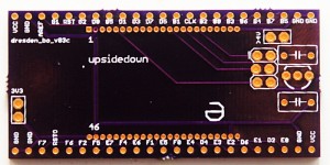
I’ll write up more about the parts themselves later, but I finally got boards made for Dresden Elektronik’s deRFmega128 modules, both made, and now assembled and tested. Briefly, these are a module with Atmel’s ATmega128RFA1 (a combined ATmega128 with a 802.15.4 2.4 Ghz transceiver on a single chip) with either a chip antenna, or a connector for your own antenna. These are TINY, and they also manage to pack a 1Mbit EEPROM on the module, for your own use. All for 21€
I’ve only tested a basic blinky thing so far, but it’s good to know that I can finally start doing something with these cool modules.
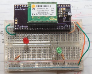
Here’s one up on a breadboard.
These modules are the same length as PJRC’s Teensy boards, but they have leads on 1.27mm pitch, not 2.54mm pitch. Lots more pins, but you’ll need some parts. For the 1.27mm socket holders, I ordered direct from Samtec. [1] Dresden recommends SLM Series, but I ordered SMS series. It may have been price, or availability, who knows. I ordered SMS-123-02-G-S, and the pins are really way too long on those. SMS-01-G-S would have been a better choice. Also, and I don’t know if the SLM would have been better, but I have a little bit of a hard time getting the modules into these sockets. They seem to “spring” out a little bit, to point that I initially thought I had failed to make my pcbs properly. Some of the pins weren’t making good contact. I have my modules mounted “upside down” with the silver RF can facing down. That’s the way the module leads are longest, and gold, and the only way they fit, when I was testing out the sockets and the modules. (Before the boards got here)
I’ve now found, that they will fit in nicely with the metal can UP and click into place nicely, but that’s not pin compatible with the AVR ISP header, or the power supply I put on the breakout.
So, I have some breakouts that work just fine, if you solder the part in, and probably well enough for development before your own boards, but I’m probably going to respin them :( The modules are cool, and they just came out with a pin compatible module, with an ARM7 core, instead of the ATmega128.
I still have a spare board from this revision though, if you are at all interested, I can send you one :)
Note, it already says rev3. That’s a story for another day :)
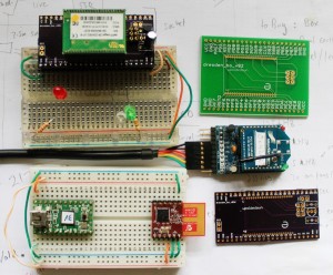
And to leave you, a picture of the different RF modules I’ve been working with here recently.
The current board files are available from https://github.com/karlp/karlnet/tree/master/experiments/dresden
The very basic blinking demo is also at github, should you really want it :)
[1] You can pretty much forget about getting 23pin headers from either digikey or mouser. Samtec were prompt, and had cheap enough shipping, relatively speaking. (I ordered a dozen)


Hi,
I am facing the same problems with the 1.27mm pitch.
If I understand you correctly
– You would try Samtec SMS-01-G-S next time
– You suggest putting the module with the silver can facing up for a better pin contact
Why did you put other components on the PCB? If I see it correctly, there is a transistor and a one or two capacitors.
Do they complete the module in a way, so just VCC and GND needs to be connected?
The 2×3 pins on the top of the PCB, these are for AVR ISP?
I’m looking for a very simple (minimal) breakout for a breadboard, which just offers all pins in a 2.54mm pitch.
You managed to use the module with only one row of pins in the breadboard.
Is that coincidence (all “important” pins are in the lower row) or did you achieve this by putting some additional lines on the PCB?
Thanks for sharing your ideas
Bye
Roland
Roland,
Correct, I would use the SMS-01-G-S next time, it’s the same, just with shorter leads. The leads on the -02- stick down below the PCB a lot.
I would put it with silver can up. It’s a bit of a push to get it into the headers, but then it “snaps” into place, and seems very secure.
After writing this post, I actually went and revised my PCBs, and had new ones made, they’re in the mail at the moment, but I expect to write a new post when those arrive and I verify that they work. (The eagle files and gerbers are at github in the same place)
The other components on the PCB are just a basic 3.3V LDO regulator. This lets me power the board, and anything connected with the 5V line from the avr programmer. Which answers your next question, yes, that 2×3 pin header is for AVR ICSP :)
As for only one row in the breadboard, I didn’t put any extra lines on the PCB, I just chose to use IO pins for the basic blink demo that were on that one side. It really depends on what pins you actually need to use. I’d imagine for a lot of uses you would be fine just using one side. I really can’t see how to make the board ever fit both sides into a normal breadboard, there’s just no more space.
The 2 header holes on the left are for attaching 3V3 directly, and there’s two more holes near the top right for adding any unregulated >4V power, to use the regulator there.
Hi Karl,
sound’s good. I’ll stay tuned for news on this channel :-)
I’ve looked at the .sch files of v3 and v4, the changes are not obvious for me,
which changes have you built in?
– Module with can facing up?
– Other socket type from Samtec?
I am still wondering why Dresden Elektronik does not sell a really simple breakout board (with all pins available in 2.54mm).
Sockets in 1.27mm are a head ache, especially with 23 pins.
I tried the Samtec “build your part number”, so you would use SMS-123-01-G-S, and Dresden Elektronik would suggest SLM-123-01-G-S?
Have you bought directly from Samtec (or via a local distributor?)
Which PCB manufacturer has produced your boards?
Ciao
Roland
v3 and v4 switch from metal can down, to metal can up. The lettering is moved, to hopefully make it a bit easier to read when the Samtec headers are soldered in. That’s all. SLM vs SMS, the SLM are lower profile. I may have skipped them based on cost? I can’t remember. I bought them directly from Samtec. The PCBs were made by DorkbotPDX. Olimex, who I’ve used before, can’t/didn’t make the holes that small, at least, not with their cheap service.
Hi Karl,
finally, the module sits on the adapter, and it’s up and running.
I have one question/proposal: If the on-board voltage regulator is not used, the ISP header’s power pin is not connected to VCC. Would it be possible to connect the ISP header’s power pin to the “main” 3V3 VCC line instead? This way the ISP header could be used without the onboard regulator.
Ciao
Roland
Hi,
I’ve just bought 2 modules deRFMega128-22c00 LP-8 from Dresden Elektronik and aI need to adapter boards from you :) Can yu send me? Whatelse do I need to see that those 2 RF modules comunicate? They come with an already loaded firmware? What firmware should I load with my AVRISP MKII programmer to see a dummy test functionality? – like button button pressed or led blinking or HyperTerminal chars sent?
Thanx for any kind of help/answer from you
That breadboard: dresden_deRFmega128_bo_breadboard_sm-300×242
is for sale? :) I would buy 2 :)
Nicholas, I have a v3 board and a v4 board spare, I’m happy to post them to you in exchange for a postcard. You can also just send the same design from https://github.com/karlp/karlnet/tree/master/experiments/dresden (v4) to any pcb fab house you like. (That is capable of the fine pitch work) (Also I’m not really setup to take payments in anyway right now)
I don’t have any of the 1.27mm pin headers spare though, you’ll have to source them yourself, either from samtec, or somewhere else. As for “demo code” they don’t come with any, and there’s no LED or buttons unless you add some yourself. Dresden does sell some full dev packs with demos and tools, if this is professional…
Sorry for the delay in replying, I was away on holidays.