Category Archives: avr

Dresden Elektronik ATmega128RFA1 breakout boards, deRFmega128

I’ll write up more about the parts themselves later, but I finally got boards made for Dresden Elektronik’s deRFmega128 modules, both made, and now assembled and tested. Briefly, these are a module with Atmel’s ATmega128RFA1 (a combined ATmega128 with a 802.15.4 2.4 Ghz transceiver on a single chip) with either a chip antenna, or a connector for your own antenna. These are TINY, and they also manage to pack a 1Mbit EEPROM on the module, for your own use. All for 21€

I’ve only tested a basic blinky thing so far, but it’s good to know that I can finally start doing something with these cool modules.

Here’s one up on a breadboard.
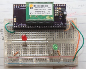
These modules are the same length as PJRC’s Teensy boards, but they have leads on 1.27mm pitch, not 2.54mm pitch. Lots more pins, but you’ll need some parts. For the 1.27mm socket holders, I ordered direct from Samtec. [1] Dresden recommends SLM Series, but I ordered SMS series. It may have been price, or availability, who knows. I ordered SMS-123-02-G-S, and the pins are really way too long on those. SMS-01-G-S would have been a better choice. Also, and I don’t know if the SLM would have been better, but I have a little bit of a hard time getting the modules into these sockets. They seem to “spring” out a little bit, to point that I initially thought I had failed to make my pcbs properly. Some of the pins weren’t making good contact. I have my modules mounted “upside down” with the silver RF can facing down. That’s the way the module leads are longest, and gold, and the only way they fit, when I was testing out the sockets and the modules. (Before the boards got here)

I’ve now found, that they will fit in nicely with the metal can UP and click into place nicely, but that’s not pin compatible with the AVR ISP header, or the power supply I put on the breakout.

So, I have some breakouts that work just fine, if you solder the part in, and probably well enough for development before your own boards, but I’m probably going to respin them :( The modules are cool, and they just came out with a pin compatible module, with an ARM7 core, instead of the ATmega128.

I still have a spare board from this revision though, if you are at all interested, I can send you one :)

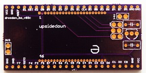
Here’s the board itself

Note, it already says rev3. That’s a story for another day :)

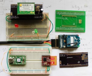
And to leave you, a picture of the different RF modules I’ve been working with here recently.

deRFmega128, Teensy v2 + MRF24J40MA, Xbee Series 1 + adafruit board

The current board files are available from https://github.com/karlp/karlnet/tree/master/experiments/dresden

The very basic blinking demo is also at github, should you really want it :)

[1] You can pretty much forget about getting 23pin headers from either digikey or mouser. Samtec were prompt, and had cheap enough shipping, relatively speaking. (I ordered a dozen)
avrdude 5.10, arduino mega 2560, command line uploading

Note: The following probably applies to the arduino UNO as well, as it also uses an onboard atmega 8u2, rather than the old raw serial converter.

Part 1 of probably many. I’ve inherited some arduino code, targetting the quite new mega2560 boards. You know, the ones that include an onboard atmega8u2, rather than the original old serial adapters. In many ways, this is a welcome step into the future. Anyway, this place doesn’t even have a regular AVR ISP programmer, and with the onboard real usb, the code running on the 8u2 is actually effectively an AVR ISP programmer itself, talking the stk500 protocol.

I am trying to move some of this code slowly out of the arduino IDE, and towards a more standard shared tree of c/c++. I have mostly succeeded in building plain hex files from the command line, based on arduino libraries (for things like LiquidCrystal and Ethernet and so on) but was having problems getting them to program. By editing arduino’s “preferences.txt” and adding “upload.verbose=true” I could see that when programming from the arduino IDE, it was using a private patched version of avrdude (5.4-arduino) with the programmer type of stk500v2, and that it was issuing a reset, via some sort of DTR toggle…


c:\tools\arduino-022\hardware/tools/avr/bin/avrdude -CC:\tools\arduino-022\hardware/tools/avr/etc/avrdude.conf -v -v -v -v -cstk500v2 -p atmega2560 -P COM5 -b 115200
... version stuff ...
Using Programmer: stk500v2
Overriding Baud Rate: 115200
avrdude: ser_open(): setting dtr
avrdude: Send: . [1b] [20] . [00] . [03] . [0e] . [11] . [01] . [01] ' [27]

Ok, so now I had enough to try and run it myself, using avrdude 5.10, as comes with recent versions of WinAVR


C:\Users\karlp>avrdude.exe -p atmega2560 -P COM5 -c stk500v2 -v -U lfuse:r:-:h -b 115200
---snip---
avrdude.exe: stk500_2_ReceiveMessage(): timeout

But, as you can see, this just timed out. Looking at the LEDs, I could see that the board wasn’t getting magically reset. With a bit of reading and searching, I found out that avrdude added a way of resetting the board, if you use the programmer type of “arduino”


Using Programmer : arduino
Overriding Baud Rate : 115200
avrdude.exe: Send: 0 [30] [20]

Interesting, following the lights on the board, I could see that this was now resetting properly, but clearly, those were not the right commands. It seems that the “arduino” programmer type, is set up to talk to the bootloader on the atmega328 of the prior versions of arduino, the Duemilanove and so on, that still had a direct USB-serial bridge, from the FTDI chip. So, if the “arduino” programmer does the reset, but the wrong protocol, looks like I’ll have to reset it myself.

I finally tried holding reset on the board, issuing the command with the programmer of “stk500v2” and immediately releasing reset. Presto!


C:\Users\karlp>avrdude.exe -p atmega2560 -P COM5 -c stk500v2 -v -b 115200
... more snipped ....
Programmer Type : STK500V2
Description : Atmel STK500 Version 2.x firmware
Programmer Model: AVRISP
Hardware Version: 15
Firmware Version Master : 2.10
Vtarget : 0.0 V
SCK period : 118.3 us

avrdude.exe: AVR device initialized and ready to accept instructions

Reading | ################################################## | 100% 0.03s

avrdude.exe: Device signature = 0x1e9801
... more snipped ...

Hooray! we’re working from the command line again. Now, if only the arduino gang’s pile of extra patches for avrdude would keep making their way back into mainline. It seems they don’t play well with others :(

ttyACM ports missing with teensy arduino on Ubuntu

So, I was reverifying my teensyduino MRF24J40 code recently, and ran into a most infuriating problem, where the /dev/ttyACMXXX devices simply didn’t exist! I could upload code to the teensy via the arduino GUI, and teensy-halfkay could see the device ok, but lsusb didn’t show the device. Weird.

I found lots of stupid terrible advice around the internet, including such insanity as “mknod blah” to simply create the devices, and even such batshit crazy suggestions like updating the rxtx jars that arduino uses. No, no, no.

I still don’t realllly know what’s going on, but someone hinted that because my device might be flooding data out the “serial” (USB CDC ACM serial) port from the instant it’s connected, the linux detection might be getting confused.

Well, I could still program the device ok, somehow, so I tried simply programming the basic teensyduino blink demo. That worked, and it started blinking, and presto, ttyACM0 got created!

NOW I could reprogram with my own mrf24j40 demo code, and I could watch the output on ttyACM0 as expected. Good news.

Except, if I unplug the device, and plug it in again, ttyACM is gone, and doesn’t come back until I reprogram with something else.

Something’s clearly broken, and it happened recently, and I’m grumpy, but at least I have a terrible workaround :(

MRF24J40 with arduino (teensyduino)

Earlier, I’d been working in pure C land, but I know not everyone uses pure C, and sometimes, the arduino environment is a nice easy way to get something prototyped.

So, I turned my mrf24j40 library into an arduino library! It supports all the basic stuff for sending and receiving 802.15.4 frames in a non-beacon network. It’s been tested so far with teensyduino, but it doesn’t use any teensy specific features, so it should work just fine on any arduino style board that has SPI and three spare pins for the reset, interrupt and chip select pins.

You can get the library from github, and like any arduino library, just extract it into your arduino/libraries directory. There are examples for tx only, rx only, and two way data.

Get the MRF24J40 arduino library

The examples are about the extent of the documentation so far, but just email me with questions!

MRF24J40 with AVR SPI (atmega32u4) part3

Update 2011 Oct 6 See Christopher’s comments below! Specifically, line 172 might need to be removed, if you’re using this with a pure mrf24j40 network, or a network that doesn’t contain xbee series 1 devices!
Update 2011 May 29 The sample code and library have been substantially upgraded. See my newer post for the details

And now I have TX working too. The microchip datasheet is _reallly_ sparse on details, and you have to go and get a copy of the actual IEEE 802.15.4 spec (either 2003, or 2006, we’re only concerned with the specification of the MAC header)

I had some problems trying to reconcile bit ordering between the IEEE spec (MSB rightmost, most of the time) and the Microhip docs (MSB leftmost, most of the time) but from there it pretty much just worked. I have yet to try out acknowledgements, I was trying to keep it pretty simple, but working code is working code.

Except… The microchip docs say that you write out one byte with the header length, one byte with the frame length, (header plus packet body) then the header, then the packet body. No gaps anywhere. Try as I might, I had to leave a two byte gap after the header, and before the packet data, when writing to the MRF24J40’s tx normal fifo. (And allow for this in the “length” fields)

I thought I had the addressing modes wrong, and my first two bytes of packet data were being used as some sort of header field I didn’t understand, but I tried out 4 different addressing modes, and in all cases, the data on the received side passed all checksums, and was only consistent with there being a _gap_ in the fifo.

Strange, but workable, as long as you know it’s there. It still makes me feel uncomfortable though.

For reference, I’m using 16 bit (short) addressing for both source and destination, PAN ID header compression (only destination PAN ID is sent) with no security.

The library code is over at github and allows sending packets to existing series one xbee listeners just like this…

mrf_reset();
mrf_init();
// set our PAN ID
mrf_pan_write(0xcafe);
// set our local source address
mrf_address16_write(0x6001);
// send something to a given node
mrf_send16(0x4202, 4, "abcd");

MRF24J40 with AVR SPI (atmega32u4) part2

Update 2011 May 29 The sample code and library have been substantially upgraded. See my newer post for the details.

Good progress last night and today. I get an interrupt for each received packet, working in both promiscuous mode and normal mode.

A fair bit of code to get here, compared to using xbees, but SPI is much much faster, and you don’t need to dick around with baud rates and getting clock timing perfect. UARTs are terrible. From the datasheet, and the little bit of information you can find on the web, it seems that these modules have some rather odd silicon errata. It seems the original datasheet was completely wrong. This is the only thing that I can think of to explain why you need to set up so many registers just to get it to work. The defaults in the silicon are all worthless. Oh well :) It works :)

Note to self: be careful to use mrf_read_long() when you want to use a long address, the address spaces overlap, so using mrf_read_short works, just doesn’t return anything useful.

Working code to get this far, with an AVR host is over at github

MRF24J40 with AVR SPI (atmega32u4) part1

Ouch, this took a lot longer to get started than I thought. SPI is meant to be easy right? All my SPI reads from the MRF24J were returning 0xff.

Turns out that, even with the /SS pin disconnected, if you don’t explicitly set it as an output pin in the DDR register, the AVR falls out of SPI mode if it ever goes low.

So, even though the pin is not connected, (I’m using a general IO pin to do chip select on the radio module) nothing worked until I explicitly made it an output.

And now, presto, I can read data from the MRF24J properly now! Now we can finally move on to the rest of this bring up.

(The MRF24J40 is an 802.15.4 module, with a SPI interface. It’s about 6€, vs about 20€ for xbees, and is on a standard 2.54mm pin spacing, instead of xbee’s 2mm spacing)

Valentines day heart chaser

I’ll be doing something a bit more romantic for Konudagur, next week, but seeing as my girlfriend was working late on Valentines day, I took a break from wireless and frequency counters and software, and whipped up a little love heart.

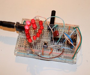
Valentines LED Heart chaser

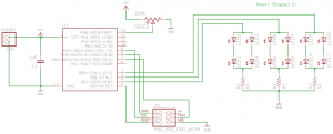
Not much to it really, just a bunch of LEDs arranged in a heart, driven straight off general IO pins of an ATtiny84, with a pot to adjust the delay between parts. The heart is 12 LEDs, in three groups of four, and can do a nice slow chase, flicker, or appear solid on.

In reality, my board has some extra current limiting resistors, as I didn’t have 12 exactly the same LEDs, and the different diode drops between the different LEDs I had meant they couldn’t share the same resistors. In reality, I also tried to hook up a pushbutton and toggle between two patterns of lights, but I have forgotten everything I learned about switch debouncing, and ran out of time.

Code is available at github, considered to be public domain.

The schematic is available at github as well, in eagle format.
Valentines chaser schematic

And, here’s a video of it, you can see the different LEDs have a slightly different colour & intensity. (And that I turned the pot the wrong way at first :)

AVR ICSP on a breadboard

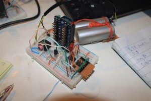
Update 2011-02-20: I made a new one for some another board, so I took a couple more pictures..

I thought I’d drawn this up a while ago, but seems I never actually got around to it. Because I prefer a proper programming editor (ie, NOT the arduino environment) I normally end up using plain old C and plain old ICSP programmers like the USBTinyISP

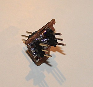
Anyway, the 2×3, 6 pin programming header doesn’t really plug into a breadboard, so I took some strip board, put a 2×3 on the top, and two 1x3s on the bottom spread out enough to cross the gap on the breadboard.

Then, just wire up the header to the MOSI/MISO/SCK/Reset pins on whatever device you’re using.Breadboard ICSP programmer in-situ in a wireless sensor node
AVR ICSP programming header view 2
AVR ICSP breadboard programming header

Frequency Counter library for atmega32u4

The guys at KHM in Cologne cooked up a very handy Frequency Counter library for arduino.  Seeing as my humidity sensor is based around the HCH1000, basically a variable capacitor, one simple way to measure the humidity is to use the sensor in an oscillator, and use the output frequency as an indicator of the humidity.  (I really need to get around to writing that up properly, it’s in progress, I promise)

Anyway, I have more boards than just an Arduino, and I also use mostly raw C.  So I’ve update the library to work with either the atmega 168 or 328 on arduino boards, but also with the atmega32u4 found on PJRC’s nifty little Teensy boards

You can get the code over on github (You need FreqCounter.c and .h)